Tools / Power Tools
Bosch GWS 18V-10 Cordless Angle Grinder Exploded View and Parts List
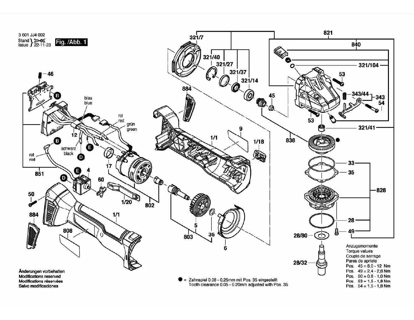
Access the official exploded view and parts breakdown for the Bosch GWS 18V-10 cordless angle grinder. Includes critical torque specifications for assembly and component identification.
Table of contents
Quick guide from the manual
This document provides an exploded view of the Bosch GWS 18V-10 cordless angle grinder, intended for service and maintenance professionals. It illustrates the internal assembly of the motor, gear housing, and electrical components. Use this guide to identify specific part numbers and ensure correct assembly using the provided torque specifications.
Assembly and Torque Specifications
When reassembling the tool, it is critical to adhere to the specified torque values to ensure safe operation and prevent damage to the housing or internal gears. The following torque values must be applied to the respective components:
- Position 45: 8.0 - 12 Nm
- Position 49: 2.4 - 2.8 Nm
- Position 50: 0.8 - 1.0 Nm
- Position 53: 1.5 - 1.8 Nm
- Position 54: 1.5 - 1.8 Nm
Additionally, note that the tooth clearance between the gear components must be adjusted to 0.08 - 0.25 mm using Position 35.
Component Overview
The diagram details the internal layout, including the motor assembly, switch mechanism, and gear head components. Wiring connections are color-coded (blue, red, green, black) to ensure correct electrical assembly. Ensure all seals (such as O-rings and gaskets) are correctly seated during reassembly to maintain the tool's integrity.
Manufacturer information
Bosch
Practical help
Common problems
Incorrect gear mesh
Ensure tooth clearance is adjusted to 0.08 - 0.25 mm using Position 35.
Loose housing or gear head
Verify that all screws are tightened to the specific torque values listed in the assembly section.
Before use
- Verify all internal components are present according to the exploded view.
- Check that all electrical wires are connected to the correct terminals (color-coded).
- Ensure all O-rings and seals are properly lubricated and seated.
- Use a torque wrench to tighten screws to the specified Nm values.
Specs in practice
- Tooth clearance
- The gap between gear teeth, which must be set between 0.08 and 0.25 mm for proper operation.
- Torque values
- The required force for tightening specific screws to prevent mechanical failure.
Images and diagrams
- The diagram shows the main housing (1/1) and the gear head assembly (821).
- Electrical connections are marked with letters (B, D, E) and colors for identification.
- The gear assembly (828) includes the spindle and necessary washers/seals.
Model compatibility
- This document is specific to Bosch GWS 18V-10 model (3 601 JJ4 002).

Manual page author
Emily Carter
User documentation editor
Prepares concise manual descriptions and highlights the most useful setup, operation, and maintenance information for readers.