Automotive / Infotainment Systems
User Manual for BYD DiLink 100F Smart Cockpit
Quick guide for the BYD DiLink 100F Smart Cockpit. Learn about interface connections, wiring, technical specifications, and installation requirements.
Table of contents
Manual images
Click an image to enlargeQuick guide from the manual
The BYD DiLink 100F is an on-board smart cockpit terminal designed for automotive use. It features an Android 14 operating system and is powered by a 12V supply. This document provides essential information regarding interface connections, technical specifications, and installation requirements for the unit.
Basic Specifications
- Chipset: Qualcomm QCA6696
- Operating System: Android 14
- Power Supply: 12V rated voltage (9V-16V input range)
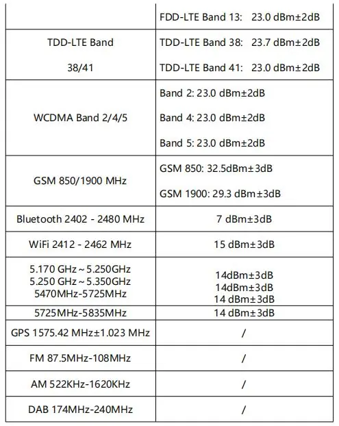
- Connectivity: BT 5.0, WiFi 2.4G/5G (802.11a/g/b/n/ac/ax), 2G/3G/4G, GNSS (GPS, GLONASS, GALILEO)
Functions
The system supports a wide range of automotive and multimedia functions, including:
- Image Center: Camera, Photo album, Driving recorder, Panoramic image.
- Multimedia Center: Music player, Video player, Karaoke.
- System Control: Air conditioning control, Intelligent voice, Tire pressure monitoring, Bluetooth phone, IVI Internet of vehicle, Application Market.
Interface Connections
The unit features multiple connectors for various vehicle systems. Ensure correct wiring based on the following mapping:
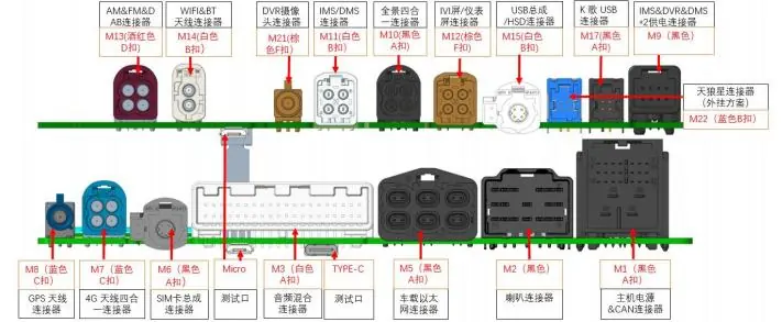
- M1: Main Connector/Power
- M2: LCD
- M3: USB Assembly
- M5: Microphone
- M8: Panoramic Camera
- M11: FM Antenna
- M12: GNSS Antenna
- M13: BT/Wi-Fi Antenna
- M14/M15: GSM/WCDMA/LTE Antenna
- M17: AUX & A2B
- M18: DMS Camera
- M20: Instrumentation Interface
- M21: Rear Microphone Interface
- M22: Karaoke System (Reserved/Not applicable overseas)
- M31: SIM Assembly
- M32: DAB
Power Wiring: The M1 interface uses red and black lines. Connect the red line to the positive pole and the black line to the negative pole. Other lines are CAN lines and do not require connection.
Installation
The physical dimensions of the unit are 160 x 184 x 60 mm. Ensure adequate space is provided for the unit and proper heat dissipation.
General Information
Temperature Ranges:
- Storage Temperature: -40°C to +85°C
- Operating Temperature: -30°C to +70°C
Voltage Ranges:
- Lower Limit: +9.0V
- Nominal: +12V
- Upper Limit: +16V
Practical help
Common problems
Karaoke system not working
The M22 interface for the karaoke system is reserved and not applicable for overseas markets.
Test USB interface not functioning
The 'Text USB' interface is for testing purposes only and is not applicable to the actual vehicle.
Before use
- Verify the vehicle power supply is within the 9V-16V range.
- Ensure the M1 power connector is wired correctly (Red: Positive, Black: Negative).
- Confirm all antenna connections (M11, M12, M13, M14, M15) are secure.
- Check that the installation space meets the 160x184x60mm requirement.
Specs in practice
- Operating Voltage
- The unit requires 12V nominal, with an operational range of 9V to 16V.
- Operating Temperature
- The unit is designed to operate between -30°C and +70°C.
Images and diagrams
- The connector diagram maps specific ports (M1-M32) to vehicle functions like antennas, cameras, and power.
- M1 is the primary power and CAN bus interface.
Model compatibility
- 5.2G WiFi frequency is restricted to indoor use only for FCC/IC compliance.
- The unit is designed for export vehicles.

Manual page author
Emily Carter
User documentation editor
Prepares concise manual descriptions and highlights the most useful setup, operation, and maintenance information for readers.