Electronics / Thermal Cameras
User Manual for CaddxFPV Eclipse 006HD Thermal Camera
Quick guide for the CaddxFPV Eclipse 006HD thermal camera. Includes wiring diagrams, OSD menu operation, serial communication protocol, and technical specifications.
Table of contents
Manual images
Click an image to enlargeQuick guide from the manual
The CaddxFPV Eclipse 006HD is a thermal imaging camera designed for FPV applications. Key operational requirements include a power supply between 9V and 24V and ensuring adequate airflow for the VTX unit, as it generates significant heat during operation. For OSD functionality, ensure your hardware is version V2.0 or higher and the software is version 240724-1_005SL_v2 or higher.
Specifications
- Detector Type: Uncooled Vanadium Oxide
- Resolution: 640x512
- Wavelength Range: 8-12μm
- FOV: 48.3°(H) x 38.6°(V) x 66°(D)
- Frame Rate: 50fps
- Power Consumption:<1.5w
- Supply Voltage: 9V-24V
- Interface: HD Interface: MIPI
- Latency: Average 20ms-22ms
Connection
The device requires specific wiring for power and data transmission. Connect the power supply (9V-24V) and ground (GND) to the designated pads. The unit also features UART communication (TX/RX) and GPIO pins (GPIO0, GPIO1, GPIO2) for advanced control. Ensure the power supply capability is sufficient ([email protected] recommended).

OSD Functions
The OSD board allows customization of the video display string. The board features a 5-button interface: up, down, left, right, and center.

- Connect the menu board to the movement.
- Power on the device.
- Press the center button to open the interface.
- Use the directional buttons to navigate the character lines.
- Press the center button to select characters or perform actions like 'DEL' (delete).
- To exit, move the cursor to the fourth line and press the center key.
Operation Mode Switching
When using the HD Thermal Imaging Camera, you must switch the Ground Side Device Mode to Race Mode:
- Press the menu key on the ground end device.
- Select the settings option.
- Navigate to the device settings.
- Find the switching mode option and select 'Race Mode' to save.
Serial Communication
The device supports serial communication for advanced control. The default baud rate is 115200bps (3.3V level). The protocol uses a header (0xFF, 0x5A), version, command ID, subcommand, payload length, payload, and CRC16 checksum. Commands are available for getting version info, image adjustment (brightness/contrast), shutter control, and hot tracking.
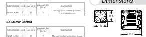
Dimensions
The unit dimensions are provided in millimeters. Please refer to the technical drawing for precise mounting hole spacing and overall unit size.
Practical help
Common problems
VTX overheating
Ensure the unit has proper airflow for heat dissipation during operation.
OSD menu not appearing
Verify that hardware is version V2.0 or higher and software is version 240724-1_005SL_v2 or higher.
Power supply instability
Ensure your power supply can handle the requirement of [email protected].
Before use
- Verify input voltage is within the 9V-24V range.
- Check all wiring connections (TX, RX, GND, Power).
- Ensure the VTX has adequate ventilation.
- Confirm firmware/software version compatibility for OSD features.
- Switch to Race Mode if using with a ground side device.
Specs in practice
- Resolution 640x512
- The thermal sensor resolution, providing clear thermal imaging.
- Supply Voltage 9V-24V
- The acceptable DC input voltage range for the device.
- Latency 22ms
- The average delay in video transmission, critical for FPV flight.
- FOV 48.3°(H)*38.6°(V)*66°(D)
- The field of view of the lens, determining how much area is visible.
Images and diagrams
- Wiring diagram: Shows pinout for TX, RX, GND, 5V0, and power inputs.
- OSD diagram: Illustrates the 5-button navigation board layout.
- Dimensions diagram: Provides physical measurements in mm for installation.
Model compatibility
- Requires switching to Race Mode for compatibility with specific ground side devices.

Manual page author
David Miller
Documentation analyst
Organizes user manual content into clear summaries, with attention to model details, product context, and everyday usability.