Electronics / Security Systems
User Guide for Digital Watchdog E.S.T. Elevated Skin Temperature System
Quick start guide for the Digital Watchdog E.S.T. system. Learn how to connect the camera, install software, configure IP settings, and set up your screening station for optimal performance.
Table of contents
Manual images
Click an image to enlargeQuick guide from the manual
This document provides essential setup instructions for the Digital Watchdog E.S.T. (Elevated Skin Temperature) system. Key requirements include a Windows 10 operating system for the monitoring PC and specific environmental conditions for accurate readings. Please note that this product is not designed for medical fever detection or disease diagnosis.
What's in the box
The contents vary by kit version:
- DW-ESTS (Complete Kit): Camera, Blackbody, LED strobe, 2x tripods, 2x power supplies, LAN cable, quick setup guide.
- DW-ESTCAM (Camera Only): Camera, LED strobe, power supply, quick setup guide.
- DW-ESTBLKB (Blackbody Only): Blackbody, power supply, quick setup guide.
Camera connection
Follow these steps to connect the camera to external devices:
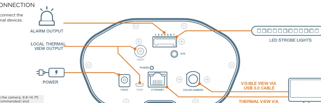
- Connect the camera to the power supply.
- Connect the Ethernet cable to the PC for data transmission.
- Connect the Blackbody to an adequate power supply and position it facing the camera at a distance of 9.8 to 14.7ft (10ft recommended).
- Use the provided ports for Alarm Output, Local Thermal View, and Video as required by your specific installation.
Software installation
The monitoring software is compatible with Windows 10 only. Follow these steps to configure the network:
- Download the EST software from the Digital Watchdog website.
- Connect the camera directly to the PC. The default camera IP is 169.254.100.100 with a subnet mask of 255.255.0.0.
- Open the Windows Run dialog (Win+R), type 'ncpa.cpl', and press Enter.
- Right-click 'Ethernet' and select 'Properties'.
- Double-click 'Internet Protocol version 4 (TCP/IPv4)'.
- Set the PC IP address to a value between 169.254.100.1 and 169.254.100.254 (ensure it does not overlap with the camera IP) and set the subnet mask to 255.255.0.0.
Setting up your screening station
For optimal performance, follow these placement guidelines:
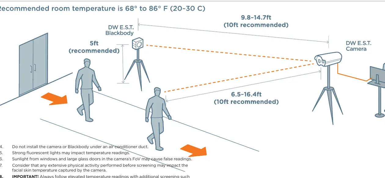
- Install the camera facing away from entrances or windows.
- Place the camera 6.5 to 16.4ft (10ft recommended) from the monitoring path.
- Position the camera at a 20-degree angle from the monitoring path.
- Ensure people walk into the camera's Field of View (FoV) rather than walking straight towards it.
- Allow the camera and Blackbody up to 5 minutes to calibrate after power-up (30 minutes for camera-only installations).
- Keep the camera's FoV clear of people and moving objects for 10 seconds when powering up the software.
Important considerations
- Recommended room temperature is 68° to 86°F (20° to 30°C) with under 80% humidity.
- Do not install the camera or Blackbody under air conditioner ducts.
- Strong fluorescent lights and sunlight from windows or glass doors may cause false readings.
- Extensive physical activity before screening may impact facial skin temperature readings.
- Always follow elevated temperature readings with additional screening, such as a medical thermometer and wellness questionnaire.
Official resources from the manual
Practical help
Common problems
False temperature readings
Ensure the camera is not facing windows or glass doors, is not under an AC duct, and is away from strong fluorescent lights.
Software connection failure
Verify the PC IP address is in the range 169.254.100.1-254 and the subnet mask is 255.255.0.0.
Inaccurate calibration
Ensure the Blackbody is powered and positioned 9.8-14.7ft from the camera. Allow 5-30 minutes for warm-up.
Before use
- Ensure the monitoring PC is running Windows 10.
- Position the Blackbody 9.8-14.7ft from the camera.
- Set the camera at a 20-degree angle to the monitoring path.
- Verify room temperature is between 68°F and 86°F.
- Clear the camera's field of view for 10 seconds during software startup.
Specs in practice
- Camera Default IP
- 169.254.100.100
- Calibration Time
- 5 minutes for full kit; 30 minutes for camera-only setup.
Images and diagrams
- The connection diagram illustrates the back panel ports including Alarm Output, Power, Ethernet, and Video.
- The setup diagram shows the recommended 10ft distance between the camera and the monitoring path, and the 20-degree angle.
Model compatibility
- Software is compatible with Windows 10 OS only.

Manual page author
David Miller
Documentation analyst
Organizes user manual content into clear summaries, with attention to model details, product context, and everyday usability.