Hvac / Heat Pumps
Start-Up and Service Instructions for Carrier 19XRV and 23XRV with Eaton LCX9000 VFD
Comprehensive guide for the start-up, operation, and service of Carrier 19XRV and 23XRV chillers equipped with Eaton LCX9000 VFD. Includes safety procedures, component identification, commissioning steps, and fault code troubleshooting.
Table of contents
Manual images
Jump to the sectionQuick guide from the manual
This document provides essential start-up and service procedures for Carrier 19XRV and 23XRV centrifugal liquid chillers equipped with Eaton LCX9000 Variable Frequency Drives (VFD). It is intended for trained and qualified service personnel. Key safety requirements include discharging DC bus capacitors for at least 5 minutes before touching internal components and verifying zero voltage with an isolated multimeter.
Safety considerations
Strict adherence to safety protocols is mandatory to prevent severe injury or death:
- Electrical Safety: High voltage is present on motor leads even when the motor is not running. Always lock out and tag electrical circuits before servicing.
- Refrigerant Safety: Never vent refrigerant relief devices indoors. Use only refrigerant or dry nitrogen for leak testing. Avoid skin and eye contact with liquid refrigerant.
- Mechanical Safety: Use appropriate mechanical equipment (hoists, cranes) for lifting heavy components. Do not step on refrigerant lines.
Commissioning the unit
The commissioning procedure must be performed by a certified technician:
- If stored outdoors, allow 24 hours for temperature stabilization.
- Enter parameters in the ICVC VFD_CONF screen.
- Install surge suppression if required.
- Verify power wiring and grounding.
- Visually inspect the drive enclosure for corrosion, moisture, or debris.
- Measure and record incoming line voltages (Vab, Vbc, Vca).
Troubleshooting the drive
The drive displays error codes on the ICVC screen. Alerts indicate a warning condition, while Alarms indicate a shutdown. Faults can be identified using the VFD_HIST screen. Common corrective actions include checking motor loading, verifying cable integrity, and ensuring proper parameter settings in the VFD_CONF screen.
Service and maintenance
Periodic inspection of all valves, fittings, and piping for corrosion or leaks is required. When removing the drive from the enclosure, ensure lifting equipment is properly rated for the specific drive weight (CH72: 198 lb, CH63: 264 lb, CH74: 617 lb). Always close refrigerant cooling isolation valves before disconnecting refrigerant lines.
Technical support
For assistance, contact the Eaton Care HVAC OEM Support Team at 1-800-752-5495 or the dedicated drives tech support at 800-322-4986. Have the Eaton General Order number, Carrier part number, and Eaton serial number ready.
Manufacturer information
Carrier Global Corporation
Practical help
Common problems
Overcurrent fault
Check for sudden heavy load increase, short circuits in motor cables, or an unsuitable motor.
Overvoltage fault
Set deceleration time longer, add a brake chopper, or monitor AC line for high voltage transients.
Ground fault
Check motor cables and motor for insulation failure or grounded conditions.
Drive overtemperature
Check coolant flow and temperature, ensure ambient temperature is within limits, and verify cooling fans are functional.
Before use
- Ensure all electrical power is shut off and locked out.
- Wait 5 minutes for DC bus capacitors to discharge.
- Verify zero voltage at input terminals using an isolated multimeter.
- Ensure refrigerant cooling isolation valves are closed before disconnecting lines.
- Verify that lifting equipment is rated for the specific drive weight.
Specs in practice
- Voltage Imbalance
- Must be 2% or less for proper operation.
- Inverter PWM Frequency
- Default is 1 (2 kHz); 0 corresponds to 4 kHz.
- Drive Weight (CH72)
- 198 lb (89.8 kg) - critical for lifting/mounting.
- Drive Weight (CH74)
- 617 lb (279.9 kg) - critical for lifting/mounting.
Images and diagrams
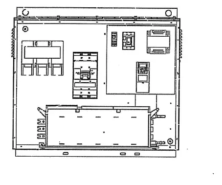
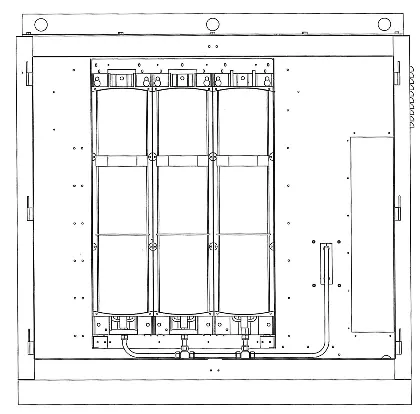
- Fig 1A/1B: Shows DC bus terminal locations for different frame sizes.
- Fig 2/7: Illustrates the procedure for checking DC bus voltage with a multimeter.
- Fig 5: Displays configuration jumper settings for the multi-purpose application board.
- Fig 8A/8B/9: Provides visual guidance for removing the drive chassis from the enclosure.
Model compatibility
- Terminal lugs are suitable for copper wire only.
- Requires PIC III controls on 19XRV or 23XRV chillers.
- Must be used with the latest revision of the Start-Up, Operation, and Maintenance Instructions for the specific chiller model.

Manual page author
David Miller
Documentation analyst
Organizes user manual content into clear summaries, with attention to model details, product context, and everyday usability.