Industrial / Electrical
Back-Up Light Wiring Diagram for 2002 Toyota Celica
Technical wiring diagram and service information for the back-up light system in the 2002 Toyota Celica, including switch operation, connector locations, and ground points.
Table of contents
Quick guide from the manual
This document provides the electrical wiring schematic for the back-up light system of the 2002 Toyota Celica. It is intended for use by technicians or owners performing electrical diagnostics or repairs on the reverse light circuit, including the reverse warning buzzer.
System operation and service hints
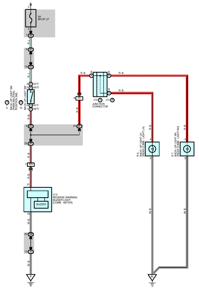
The back-up light system is activated by the back-up light switch (or park/neutral position switch for automatic transmissions). The circuit is closed when the shift lever is placed in the R (Reverse) position.
- Automatic Transmission (A/T): The switch (P1) is closed between terminals 3 and 2 when the shift lever is in the R position.
- Manual Transmission (M/T): The switch (B1) is closed between terminals 2 and 1 when the shift lever is in the R position.
Wiring and components
The system is powered by a 5A fuse (BK/UP LP). The circuit includes a junction connector (J12, J13) that distributes power to both the left-hand (R6) and right-hand (R7) rear combination lights. The circuit also connects to the C12 reverse warning buzzer located in the combination meter.
Connector and ground locations
The manual provides specific locations for connectors and ground points to assist in troubleshooting:
- Junction Block Connectors: IB, II, IM, 2C, and 2F are located in various areas including the engine room and instrument panel brace.
- Wire Harness Connectors: IE5 and II1 connect the engine room main wire to the instrument panel and floor wires.
- Ground Points: The system grounds at point IF (Instrument Panel Brace RH) and BL (Back Panel Center).
Manufacturer information
Toyota Motor Corporation
Practical help
Common problems
Back-up lights fail to illuminate when in Reverse
Check the back-up light switch (P1 for A/T or B1 for M/T) for continuity when the shift lever is in the R position. Verify the 5A BK/UP LP fuse.
Reverse warning buzzer does not sound
Inspect the connection to the C12 buzzer module and verify the circuit integrity from the back-up light switch.
Before use
- Verify the 5A BK/UP LP fuse is intact.
- Ensure the shift lever is fully engaged in the R position.
- Check for continuity at the back-up light switch terminals.
- Inspect ground points IF and BL for corrosion or loose connections.
Specs in practice
- Closed (Switch)
- Indicates the switch is conducting electricity (ON state) when the gear is in Reverse.
Images and diagrams
- The diagram shows the flow from the power source through the switch to the rear lights and the reverse buzzer.
- Red lines (R-B, R-L) indicate power-carrying wires.
- White lines (W-B) indicate ground-side wires.
- J12/J13 represents the junction connector splitting the circuit to the left and right tail lights.
Model compatibility
- Diagram applies specifically to 2002 Toyota Celica models.
- Switch operation differs between A/T (Park/Neutral Position Switch) and M/T (Back-up Light Switch) versions.

Manual page author
Michael Turner
Technical manual editor
Reviews PDF manuals for structure, safety notes, and practical product details so readers can find the right information quickly.