Home / Garage Door Openers
Receiver Logic Board Replacement for Chamberlain 050DCTBFMC
A comprehensive guide for replacing the receiver logic board on Chamberlain garage door openers (models 050DCTBFMC and 050DCTBFLKMC). Includes step-by-step installation, remote programming, travel adjustment, and safety system testing.
Table of contents
Manual images
Click an image to enlargeImportant Information
This guide provides instructions for replacing the receiver logic board on Chamberlain garage door opener models 050DCTBFMC and 050DCTBFLKMC. The new logic board includes updated firmware with an Obstruction Notification feature that signals if the opener senses resistance. Warning: Always disconnect all electric and battery power before performing any service or maintenance to prevent serious injury or death.
Installation
Before beginning, ensure you have the myQ serial number from the provided label to add your opener to your myQ account after installation.
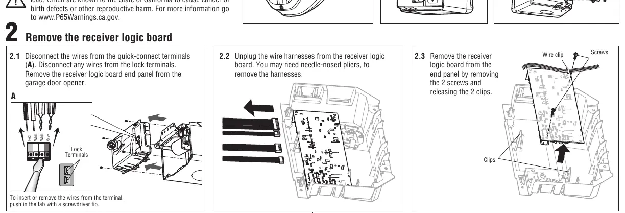
Removing the Old Board
- Disconnect electrical and battery power.
- Remove the light lens by pulling the top side and swinging it down; squeeze the clips to remove it from the end panel.
- Disconnect wires from the quick-connect and lock terminals.
- Unplug wire harnesses from the receiver logic board (needle-nosed pliers may be required).
- Remove the two screws and release the two clips to remove the board from the end panel.
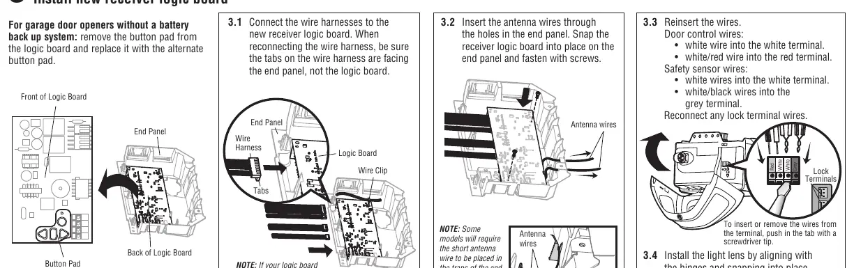
Installing the New Board
- Connect wire harnesses to the new board, ensuring tabs face the end panel.
- Insert antenna wires through the holes in the end panel.
- Snap the board into place and secure it with screws.
- Reinsert wires into the correct terminals:
- Door control wires: White wire to white terminal, white/red wire to red terminal.
- Safety sensor wires: White wires to white terminal, white/black wires to grey terminal.
- Reinstall the light lens, ensuring antenna wires hang straight down.
Programming
To program a remote control:
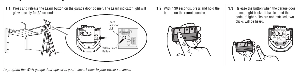
- Press and release the Learn button on the garage door opener. The Learn indicator light will glow steadily for 30 seconds.
- Within 30 seconds, press and hold the button on the remote control.
- Release the button when the garage door opener light blinks. If light bulbs are not installed, two clicks will be heard.
Adjustment
Programming the travel limits is required for safe operation.
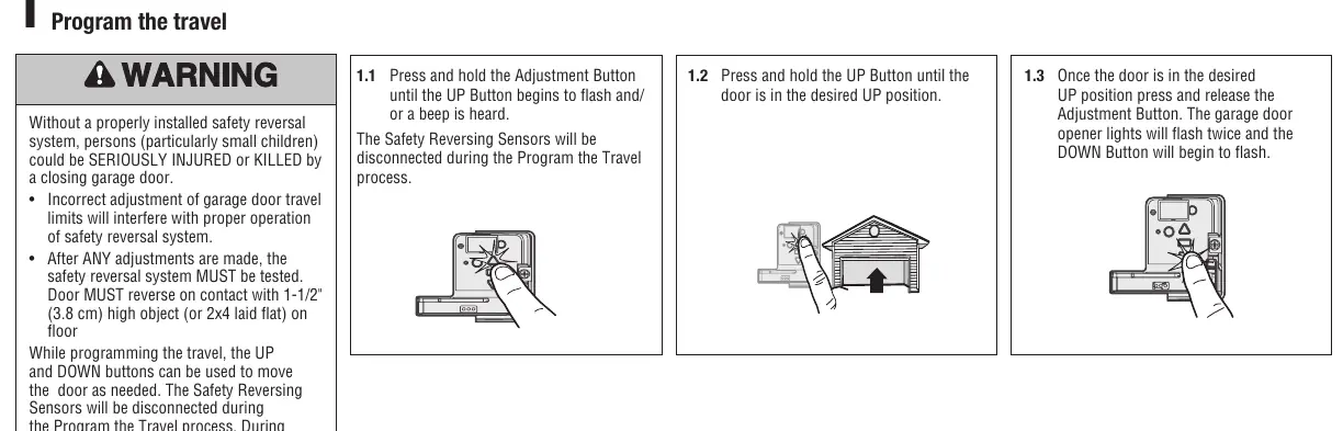
- Press and hold the Adjustment Button until the UP button flashes or a beep is heard.
- Press and hold the UP button until the door reaches the desired UP position.
- Press and release the Adjustment Button; the lights will flash twice and the DOWN button will begin to flash.
- Press and hold the DOWN button until the door reaches the desired DOWN position.
- Press and release the Adjustment Button; the lights will flash twice.
- The system will then perform an automatic force setup by moving the door open and closed.
Testing and Safety
After any adjustments, the safety reversal system must be tested.
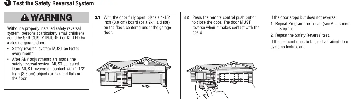
- Safety Reversal Test: Place a 1-1/2 inch (3.8 cm) board or a 2x4 laid flat on the floor under the garage door. Close the door using the remote. The door must reverse upon contact with the board.
- Protector System Test: Open the door and place an obstruction in the path. Attempt to close the door using the remote; the door should not move more than an inch.
Manufacturer information
Chamberlain
Practical help
Common problems
Door stops but does not reverse during safety test
Repeat the Program the Travel process and then repeat the Safety Reversal test.
Programming timed out (lights flash 5 times)
The programming window has expired. Restart the Program the Travel process from step 1.
Safety sensors not working
Check if the LED on the safety sensor is off. If off, the sensor is misaligned or obstructed. Clear the obstruction or align the sensors.
Before use
- Disconnect all electric and battery power.
- Wear protective gloves and eye protection.
- Verify you have the myQ serial number from the provided label.
- Ensure the light lens is removed to access the board.
- Have a screwdriver ready for terminal tabs.
Specs in practice
- 050DCTBFLKMC
- Replaces WFLK/TBLK/TBLKMC models.
Images and diagrams
- The wiring terminals are color-coded: Red, White, and Grey.
- The Learn button is located on the main opener unit, usually near the light lens area.
- The antenna wires must be routed through the end panel holes during installation.
Model compatibility
- Compatible with specific Chamberlain garage door opener models.
- Not for use with openers requiring different logic board configurations.

Manual page author
Emily Carter
User documentation editor
Prepares concise manual descriptions and highlights the most useful setup, operation, and maintenance information for readers.