Automotive / Backup Cameras
User Manual for Dakota Micro OverView DMOV-DWH7C Wireless Monitor and Camera System
Quick guide for the Dakota Micro OverView DMOV-DWH7C wireless monitor and camera system. Includes setup, pairing, wiring instructions, event trigger configuration, and menu settings.
Table of contents
Manual images
Click an image to enlargeQuick guide from the manual
The Dakota Micro OverView DMOV-DWH7C is a wireless monitoring system designed for vehicle backup and observation. This guide covers the essential setup, power connection, and operation of the monitor and camera. Always ensure the monitor is in single-view mode before attempting to pair cameras, as pairing will not function in split-screen or scan modes.
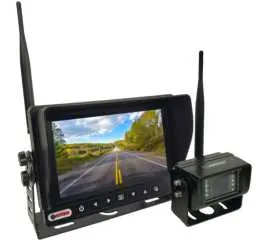
Included components
- 7-inch HD digital wireless waterproof monitor
- HD digital 85° wireless camera
- 12V cigarette lighter power adapter
- Hardwire power adapter with t-tap clips
Power connection
12V Cigarette Lighter: Simply attach the power input connector on the monitor to the provided 12V cigarette lighter adapter and plug it into your vehicle's power source.
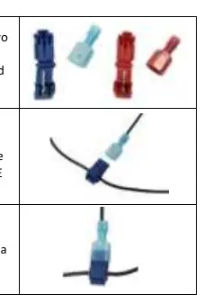
Hardwire Power: For permanent installation, use the provided hardwire power adapter. Connect the red wire to power and the blue wire to ground using the included t-tap clips. Warning: The hardwire connection must be attached to a maximum 7.5A fused circuit to prevent damage.
AC Power: To power the system via an AC outlet, you must purchase the optional Dakota Micro AC power adapter (Part number: DM-PA3).
Event trigger wire operations
The system features event trigger wires that automatically switch the monitor to a specific camera when a 12V positive signal is detected (10.5V to 16.9V). The most recent event becomes the primary display.
- Camera 1: Brown wire
- Camera 2: Yellow wire
- Camera 3: White wire
- Camera 4: Blue wire
Monitor operation and pairing
To pair a camera with the monitor:
- Plug the monitor into a power source.
- Ensure the monitor is in single-view mode (not split-screen or scan mode).
- Plug the camera into a power source.
- Press the MENU button on the monitor.
- Use the Left/Right arrows to select the Pair icon.
- Press the OK button.
- The monitor will display "Please press pair key on Tx side 20" and begin scanning for the camera signal.
If the signal is not found, unplug the camera for 10 seconds and repeat the process.
Menu settings
The monitor menu allows for various adjustments:
- Picture Setting: Adjust brightness, contrast, and color (0-9 scale).
- Normal/Mirror: Adjust camera viewing orientation.
- Multiscreen Mode: Select layout for split, triple, or quad view.
- System Settings: Adjust date/time, turn off specific camera screens, change PAL/NTSC, and toggle day/night mode.
- Autorotation: Configure automatic channel switching and duration.
- Reverse Guidelines: Toggle or adjust on-screen parking guidelines.
Practical help
Common problems
Monitor displays 'No Signal'
Ensure the camera is powered and correctly paired to the monitor.
Cannot pair camera
Ensure the monitor is not in split-screen or SCAN mode. Pairing only works in single-view mode.
Camera signal not found during pairing
Unplug the camera from its power source for 10 seconds, then plug it back in and retry the pairing process.
Before use
- Verify the 12V power source is active.
- Ensure the hardwire connection is on a MAX 7.5A fused circuit.
- Confirm the camera is not powered during the initial pairing setup.
- Ensure the monitor is set to single-view mode before pairing.
- Check that all event trigger wires are connected to a 10.5V-16.9V positive source if using the trigger feature.
Specs in practice
- Field of View
- The 2.8mm lens provides an 85° horizontal and 120° diagonal view.
- Event Trigger Voltage
- The trigger circuit requires a 10.5V to 16.9V positive signal to activate.
Images and diagrams
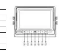
- Monitor Buttons: 1. Power, 2. Left/Volume-, 3. Right/Volume+, 4. Menu/Esc, 5. Down/CH, 6. Up/CH, 7. OK/Camera Toggle.
- Event Trigger Colors: Brown (Cam 1), Yellow (Cam 2), White (Cam 3), Blue (Cam 4).
Model compatibility
- Supports up to 4 digital wireless cameras.
- Requires optional DM-PA3 adapter for AC power operation.

Manual page author
Michael Turner
Technical manual editor
Reviews PDF manuals for structure, safety notes, and practical product details so readers can find the right information quickly.