Automotive / Backup Cameras
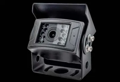
Installation Guide for Brandmotion Heavy Duty AHD Camera 1080p FLTW-1000
Step-by-step installation guide for the Brandmotion Heavy Duty AHD Camera 1080p (FLTW-1000). Includes mounting instructions, wiring, and camera settings for parking lines and image mirroring.
Table of contents
Manual images
Click an image to enlargeQuick guide from the manual
This document provides installation instructions for the Brandmotion Heavy Duty AHD Camera 1080p (FLTW-1000). The installation is rated at a difficulty level of 3 out of 5 wrenches and typically takes between 1 hour 30 minutes and 2 hours to complete. Required tools include a screwdriver, drill, 1-inch hole saw, and electrical tape.
Kit contents
Ensure all components are present before beginning the installation:
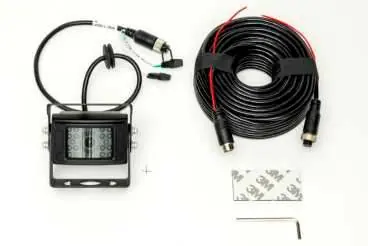
- 1x Heated HD Camera
- 1x 20m 4-Pin Extension Cable
- 1x Allan Key
- 1x 3M Tape Pad
Camera mounting
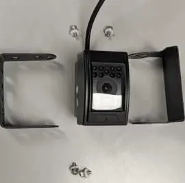
- Remove the 4 Allen screws located on the sides of the camera to detach the mounting bracket and visor.
- Identify an appropriate mounting location and align the foot bracket to ensure sufficient space for the camera body.
- Secure the mounting foot using self-tapping screws or a bolt and nut.
- Use a 1-inch hole saw to drill a hole for the camera harness.
- Feed the harness through the hole and fit the grommet. Note: The grommet may not be water-tight; the use of silicone or other sealing agents is recommended.
- Reattach the camera and visor to the mounting bracket. Ensure the microphone is positioned on the right side when facing the camera for an upright installation.
Power connection
The camera is powered via a 4-pin Aviator harness. Connect the camera to the harness to establish the power and video signal connection.
Camera settings
The camera connector features two loop wires (WHITE and GREEN) that allow for configuration adjustments:
- Green loop wire: Controls parking lines. Unplug the loop cap to enable parking lines.
- White loop wire: Controls mirrored image. Unplug the loop cap to unmirror the image. Plug in the loop cap for rear-facing camera use; unplug the loop cap for front-facing camera use.
Practical help
Common problems
Water leakage at the harness hole
The provided grommet may not be fully water-tight. Apply silicone or other sealing agents around the hole.
Parking lines are not visible
Unplug the loop cap on the green wire to enable the parking lines.
Image is mirrored incorrectly
Adjust the white loop wire. Plug in the cap for rear-facing use; unplug the cap for front-facing use.
Before use
- Ensure you have a 1-inch hole saw.
- Verify you have a drill and screwdriver.
- Have electrical tape ready for connections.
- Confirm the mounting location has enough clearance for the camera body.
- Check that all kit contents are present.
Specs in practice
- Green loop wire
- Toggles parking lines on/off.
- White loop wire
- Toggles mirrored image on/off (front vs. rear facing).
- 4-pin Aviator harness
- Standard connector for power and video signal.
Images and diagrams
- The camera bracket is removed by unscrewing the 4 Allen screws on the sides of the unit.
- Loop wires are located on the end of the camera connector cable.
Model compatibility
- Universal vehicle application.

Manual page author
Emily Carter
User documentation editor
Prepares concise manual descriptions and highlights the most useful setup, operation, and maintenance information for readers.