Industrial / Vehicle Barriers
Installation Guide for DoorKing 1601-268-P-5 Barrier Gate Arm Hardware Kit
Comprehensive installation guide for the DoorKing 1601-268-P-5 barrier gate arm hardware kit. Includes step-by-step instructions for bracket mounting, wire harness installation, power supply mounting, and various arm assembly...
Table of contents
Manual images
Click an image to enlargeImportant Information from the Manual
This document provides installation instructions for the DoorKing 1601-268-P-5 barrier gate arm hardware kit. It is designed for 1600 series barrier gate operators. Warning: Moving arms can cause vehicle damage, severe injury, or death. Always stay clear of the arm. Ensure all power is turned OFF to the operator before beginning installation.
Standard Arm Bracket Installation
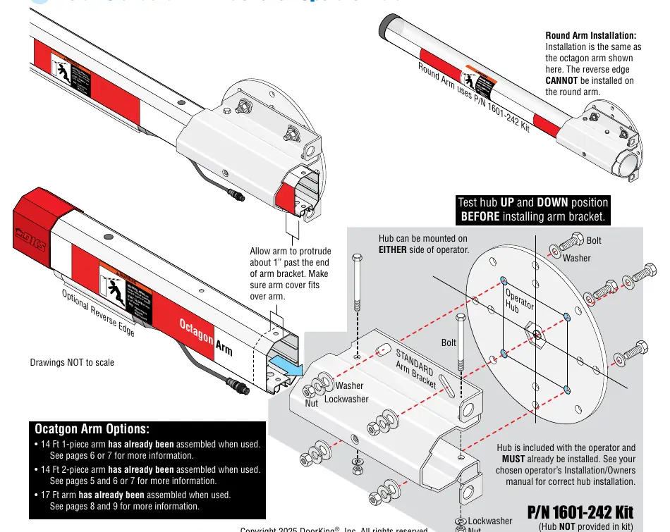
The hub must be installed on the operator before mounting the bracket. The hub can be mounted on either side of the operator. Test the hub in both UP and DOWN positions before installing the arm bracket. Secure the bracket to the operator hub using the provided bolts, washers, lockwashers, and nuts.
Wire Harness Installation
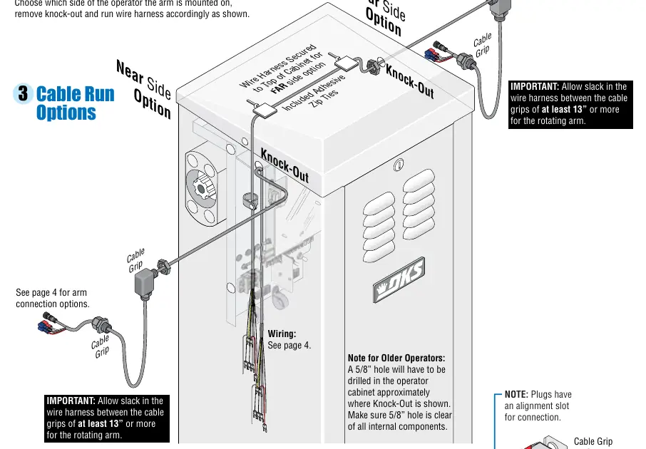
The wire harness (8080-356) is required for specific kits. Choose the side of the operator for arm mounting and remove the knock-out. Route the wire harness through the cabinet. Important: Allow at least 13 inches of slack in the wire harness between the cable grips to accommodate the rotating arm. For older operators, a 5/8 inch hole may need to be drilled in the cabinet.
Power Supply Mounting
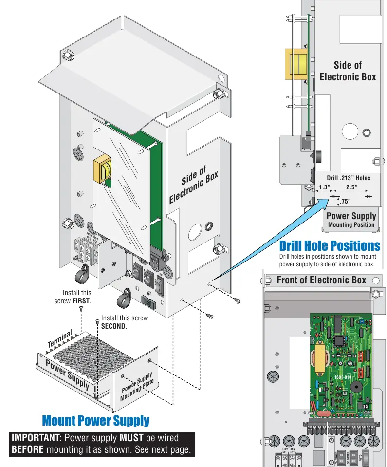
The power supply must be wired before mounting. Drill holes in the side of the electronic box as specified (1.3 inches and 2.5 inches spacing). Secure the power supply mounting plate to the side of the electronic box using the provided screws.
Wiring to Operator
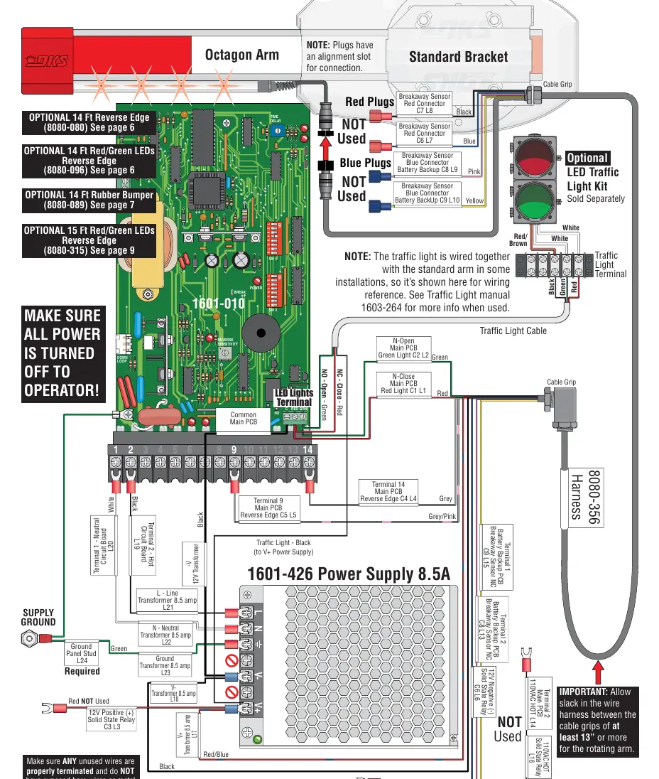
Connect the wire harness to the main PCB and power supply. Ensure all unused wires are properly terminated and do not have exposed bare wires. Refer to the wiring diagram for specific terminal connections (e.g., Terminal 14 for Reverse Edge, Terminal 9 for Common). Plugs have an alignment slot for connection.
Arm Assembly Options
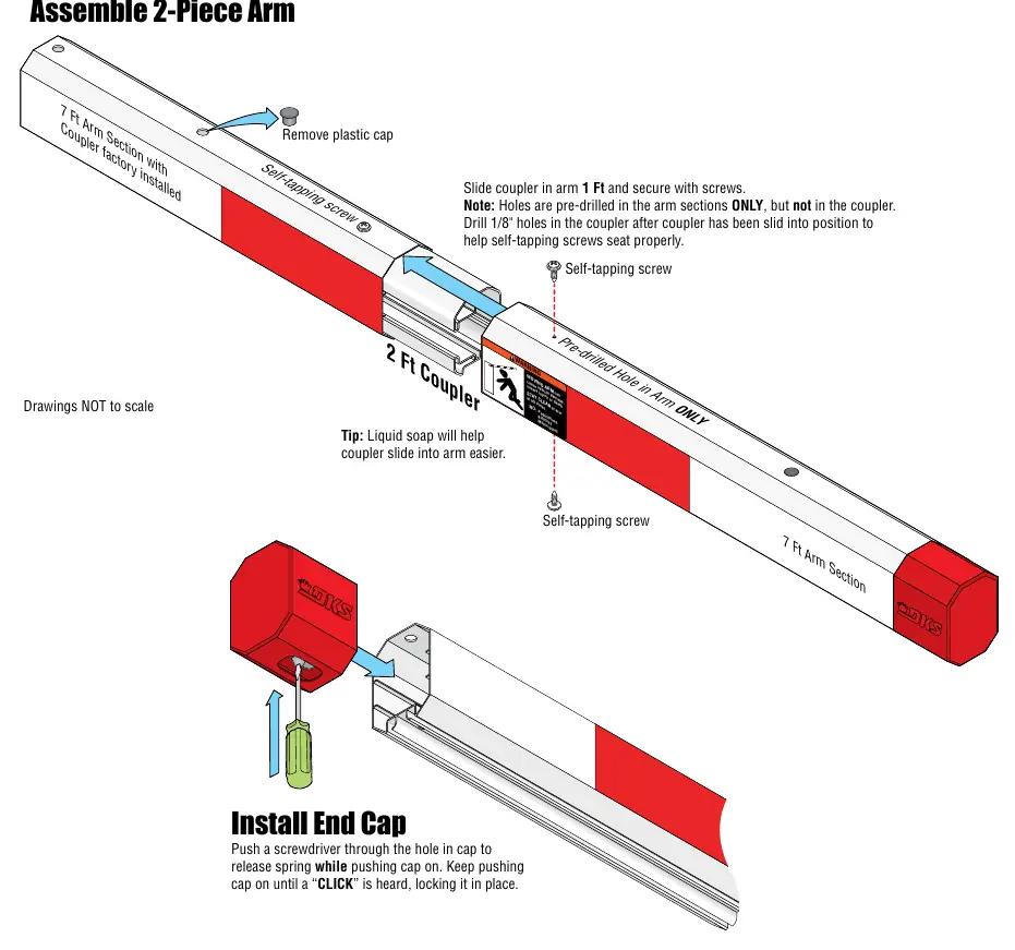
- 14 Ft 2-Piece Octagon Arm: Assemble the two 7 ft sections using the 2 ft coupler. Slide the coupler 1 ft into each arm section and secure with self-tapping screws. Drill 1/8 inch holes in the coupler after sliding it into position to ensure screws seat properly.
- 17 Ft Octagon Arm (1602 Only): Designed for 1602 operators. Uses a 14 ft arm with a 3 ft extension. Use the 1 ft and 2 ft couplers to join sections. Drill .125 inch holes on top and bottom 3 inches from the end of the arm to secure.
Safety Accessories
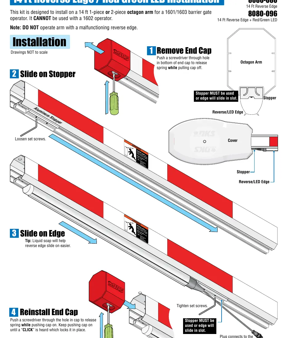
Reverse edges and rubber bumpers are highly recommended for safety. When installing a reverse edge, ensure the stopper is used and tightened so the edge does not slide in the slot. Use liquid soap to help the reverse edge or rubber bumper slide onto the arm easier. For older existing arm covers, use the provided template to cut a notch for the reverse edge.
Practical help
Common problems
Arm cover does not fit
Ensure the arm protrudes about 1 inch past the end of the arm bracket.
Reverse edge slides in the slot
Ensure the stopper is installed, pushed against the reverse edge, and tightened securely.
Wire harness is too tight
Ensure there is at least 13 inches of slack in the wire harness between the cable grips to allow for arm rotation.
Before use
- Ensure all power is turned OFF to the operator.
- Test the operator hub in UP and DOWN positions before installing the arm bracket.
- Verify the operator model (1601, 1602, or 1603) to ensure kit compatibility.
- Check if a reverse edge is required for safety.
- Ensure the stopper is used for all reverse edge installations.
Images and diagrams
- Standard Bracket Installation: Shows mounting the bracket to the operator hub using bolts, washers, and lockwashers.
- Wiring: Details connections for the 8080-356 harness to the main PCB and power supply.
- 2-Piece Arm Assembly: Illustrates the use of the 2 ft coupler and self-tapping screws to join arm sections.
Model compatibility
- 1602 operator: Requires specific 17ft arm assembly kit; cannot use 1601/1603 kits.
- Round arm: Reverse edge cannot be installed on round arms.
- 14 Ft 2-Piece Arm: Designed for 1601 or 1603 operators only.

Manual page author
Michael Turner
Technical manual editor
Reviews PDF manuals for structure, safety notes, and practical product details so readers can find the right information quickly.