Industrial / Vehicle Barriers
Installation and Parts Guide for DoorKing 1625-616 Wedge Barrier
Comprehensive installation and parts assembly guide for the DoorKing 1625-616 16FT Wedge Barrier. Includes detailed technical drawings, component lists, and installation specifications.
Quick answers from the manual
Quick answer
- This document is an assembly and parts manual for the DoorKing 1625-616 16FT Wedge Barrier. It provides technical drawings, dimensions, and a comprehensive list of components required for installation. p. 1, 2, 3, 4
Key actions
- Install anchor bolts p. 1
Technical specifications
| Parameter | Value | Meaning | Pages |
|---|---|---|---|
| Opening | 15.5 Feet (188in) | Clearance width | p. 1 |
Where to find it in the PDF
- Overview and Dimensions p. 1
- Parts List p. 2
- Assembly Details p. 3, 4
Table of contents
Manual images
Click an image to enlargeQuick guide from the manual
This document serves as an assembly and parts manual for the DoorKing 1625-616 16FT Wedge Barrier. It provides technical drawings, dimensions, and a comprehensive list of components required for installation. Please note that this is a technical drawing document and does not contain operational instructions for the barrier system.
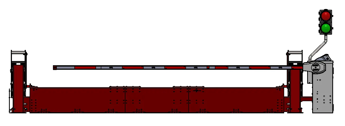
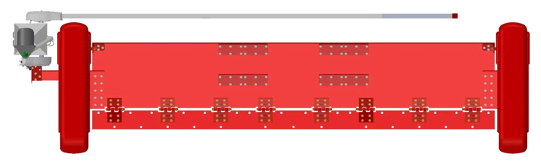
Product dimensions and overview
The wedge barrier is designed for a 15.5 Feet (188in) opening with a 17 Feet Octagon Arm. The system includes various views including Top, Side, and Front views to assist with site planning and installation.
Installation requirements
Important notes for installation include:
- Components sold separately: The operator, arm, edge, and traffic lights are not included with this unit and must be purchased separately.
- Anchor bolts: These are not provided. It is recommended to use 3/4 in - 1.0 in diameter anchor bolts (61 required).
- Compliance: Ensure all installations follow the provided technical drawings and local safety regulations.
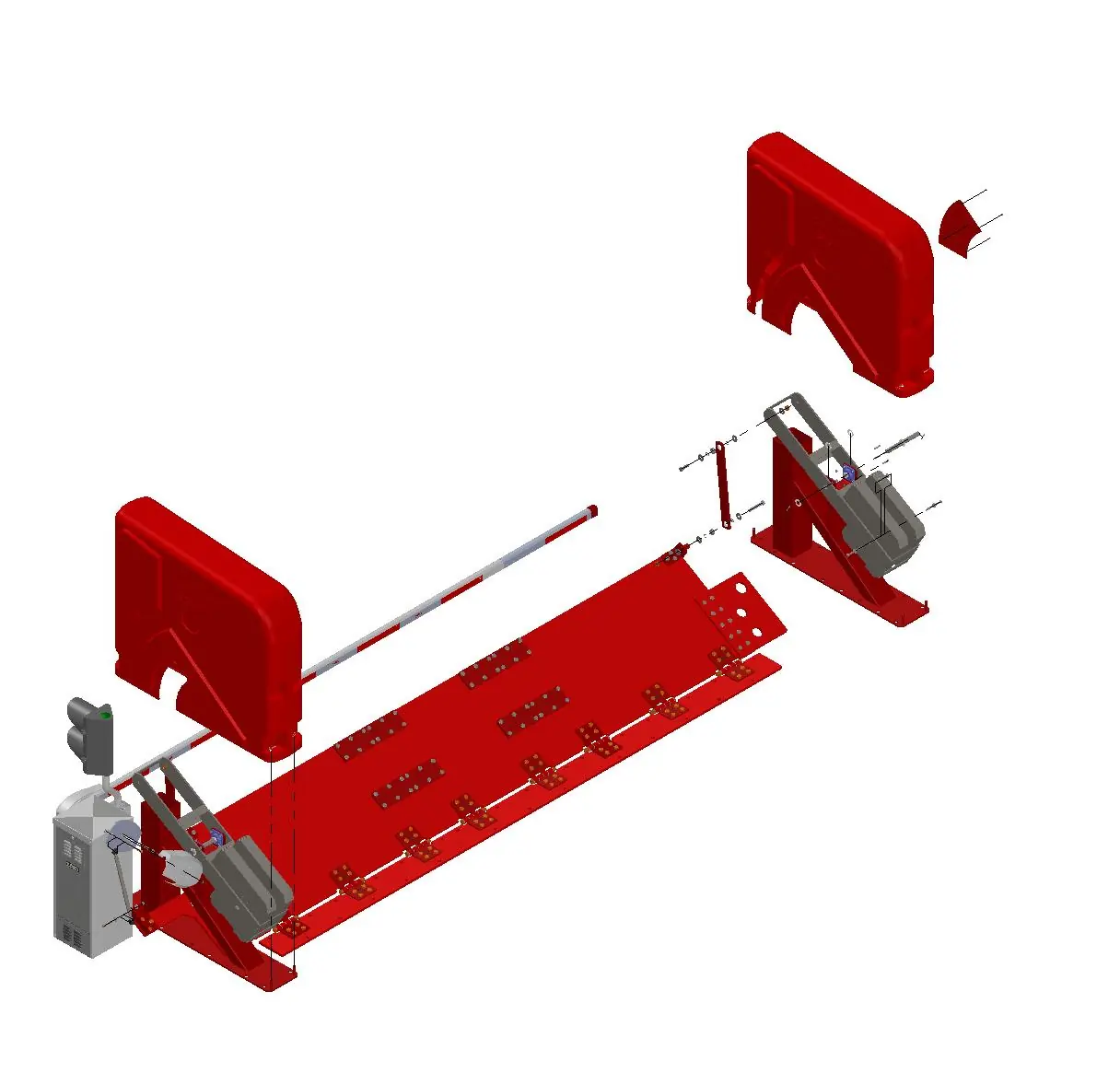
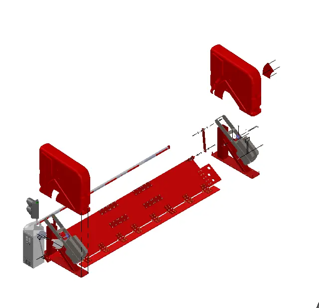
Parts list and assembly
The manual provides detailed parts lists and assembly diagrams (Detail B and Detail C) to assist in the construction of the barrier. Key components include hinge bearings, link bars, wedge posts, and various mounting plates. Refer to the provided diagrams for the correct placement of bolts, washers, and nuts during assembly.

Practical help
Before use
- Verify all parts against the provided parts list
- Ensure 3/4 in - 1.0 in diameter anchor bolts are available for installation
- Confirm that the operator, arm, edge, and traffic lights have been acquired separately
- Check site dimensions against the provided 15.5ft opening specification
Specs in practice
- Anchor Bolts
- 3/4 in - 1.0 in diameter recommended (not provided)
Images and diagrams
- Page 1: Overall dimensions and views
- Page 2: Parts list and component identification
- Page 3: Assembly Detail B
- Page 4: Assembly Detail C
Model compatibility
- Operator, Arm, Edge, and Traffic Lights are sold separately.

Manual page author
Emily Carter
User documentation editor
Prepares concise manual descriptions and highlights the most useful setup, operation, and maintenance information for readers.