Health / Assistive Technology
User Manual for Drive Full-Electric Lightweight Bariatric Bed Series
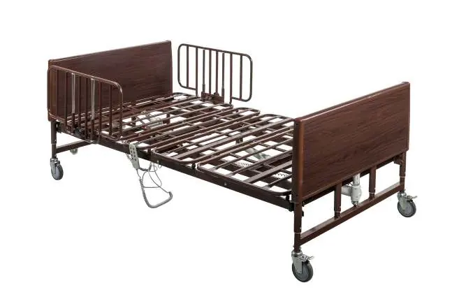
Comprehensive user manual for the Drive Full-Electric Lightweight Bariatric Bed Series (15302LW, 15303LW). Includes assembly instructions, operation guide, safety warnings, maintenance, and troubleshooting.
Table of contents
Manual images
Click an image to enlargeQuick Start Guide
This manual provides instructions for the Drive Full-Electric Lightweight Bariatric Bed Series (15302LW and 15303LW). Before using the bed, ensure all components are inspected for damage, the bed is assembled correctly, and all safety warnings are understood. The bed is not intended for patient transport.
Assembly Instructions
Tools Required: Wire cutters, utility knife.
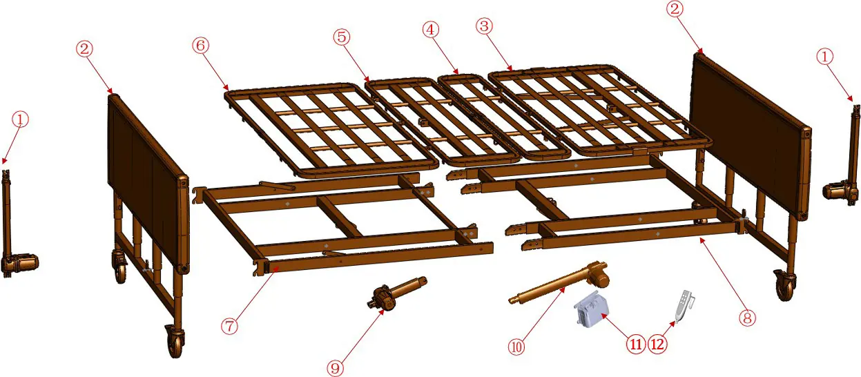

- Frame Assembly: Place both ends of the frame on the ground and align the four flanges with the receptacles. Slide the two sides together until flanges are fully inserted.
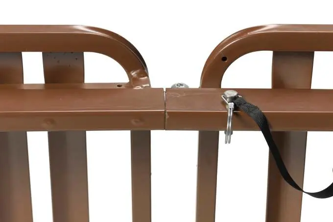
- Securing: Secure the frame/sleep surface with the provided cotter pin and lock with the attached clasp on both sides.
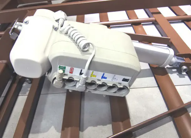
- Motor Connection: Locate the motor connecting wires attached to each bed end. Insert the wires into the corresponding color-coded outlets on the control box.
- Head/Foot Boards: Align the frame mounting hooks over the bed end mounting pins and push down to secure. Engage the Slide Locks over the frame hooks to prevent separation.
Bed Operation
The bed is operated using a 4-function hand-held pendant:
- Top Row: Raises/lowers the Head Section.
- Second Row: Raises/lowers the Foot Section.
- Third Row: Simultaneously raises/lowers Head and Foot Sections.
- Fourth Row: Raises/lowers the Bed surface height.
The hand control illuminates when the bed is plugged into a grounded outlet or when a 24V battery (not included) is installed. The battery backup is for emergency use only to return the bed to a horizontal position during power failure.
Bed Rail Installation
Only use compatible Drive DeVilbiss Healthcare side rails. Locate the label on the head section of the frame. Align the fixed clamp jaw in front of the bed frame rail, place the movable clamp jaw on top, and turn the knob clockwise until tight.
Safety and Warnings
- Weight Capacity: 48" bed: 750 lbs; 54" bed: 1000 lbs (includes patient, mattress, and all accessories).
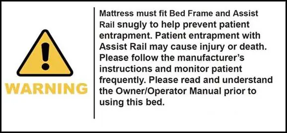
- Entrapment: Mattress must fit snugly against the bed frame and side rails. If a patient's condition increases entrapment risk, keep the bed in a flat position when unattended.
- Operation: Do not operate the bed if components are damaged. Keep hands and feet clear of the frame during operation.
- Oxygen: Do not use near open flames or explosive gases. Use only nasal or masked type oxygen equipment.
Maintenance and Cleaning
- Cleaning: Unplug the bed before cleaning. Use mild detergent and warm water. Do not submerge the bed frame or electrical components. Do not use steam cleaners or power washers.
- Lubrication: Lubricate caster roller and swivel bearings with light machine oil.
- Checks: Regularly inspect all cables for damage, check welds, and ensure all bolts are tightened.
Troubleshooting
If the bed does not move:
- Check if the bed is plugged into a wall outlet.
- Ensure the pendant connection is secure.
- If thermal protection has tripped due to excessive use, allow the bed to sit for up to 30 minutes to reset.
- Check for obstructions under the bed.
Technical Specifications
- Electrical: 100-240VAC, 50/60Hz.
- Duty Cycle: 2 min ON / 18 min OFF.
- Operating Temperature: 10°C to 40°C (50°F to 104°F).
Manufacturer information
Drive Medical
Practical help
Common problems
Bed movement does not occur when pendant button is pushed
Check power connection, ensure pendant is connected to the motor housing, allow thermal protection to reset (up to 30 mins), or check for obstructions.
Bed will not raise or lower
Ensure the drive shaft is properly installed and connected to both bed end gear boxes. Ensure bed ends are installed as a set (Head/Foot labels).
Motor cannot be installed to bed deck
Ensure both white motor blocks are in the fully retracted position by plugging in the power cord and depressing the down buttons on the hand pendant.
Before use
- Inspect all components for damage, scratches, or dents.
- Ensure motor connections to the control box are secure.
- Verify that the mattress is the correct size and fits snugly.
- Lock all casters to prevent unintended movement.
- Ensure the bed is in the lowest position when unattended.
Specs in practice
- Safe Working Load
- 48" bed: 750 lbs; 54" bed: 1000 lbs. Includes patient, mattress, and all accessories.
- Operating Temperature
- Must be between 10°C and 40°C (50°F to 104°F). Wait 30 minutes if stored outside this range.
Images and diagrams
- Control Box: Features color-coded outlets for motor wires (Head, Foot, Hi/Lo).
- Hand Pendant: Buttons are arranged by function (Head, Foot, Both, Height).
Model compatibility
- Only use Drive DeVilbiss Healthcare compatible side rails.
- Mattress height must be a minimum of 5-1/2 inches.
- Use only authorized Drive DeVilbiss replacement parts.

Manual page author
David Miller
Documentation analyst
Organizes user manual content into clear summaries, with attention to model details, product context, and everyday usability.