Health / Mobility Aids
User Manual for Drive 13085LN and 13085RN Seat Lift Chair Table
Quick guide for the Drive 13085LN and 13085RN Seat Lift Chair Table. Includes assembly instructions, operating procedures, safety warnings, and maintenance tips.
Table of contents
Quick Guide
The Drive Seat Lift Chair Table is designed to provide a convenient surface for users seated in chairs or couches. Important: This table is not a lift assist device and must not be used to support more than 25 lbs. Always ensure the base is positioned correctly under the chair or couch to prevent tipping.
Assembly Instructions
Tools required: Phillips screwdriver and two 7/16” wrenches.
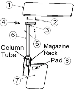
- Place the base (#7) under the chair (left side for 13085LN, right side for 13085RN) with the magazine rack opening facing the rear. Place the front leg of the chair on the positioning pad (#8).
- Stand the column (#6) on end. Ensure the trip rod is visible in the rectangular tube but not protruding. Shake the column if necessary until the rod drops.
- Insert the trip handle (#4) into the column (#6) with the rounded side up, ensuring it rests on top of the rod.
- Place the top (#1) on a flat surface with the top bracket facing upward. Insert the column (#6) into the top bracket. Align the holes in the column foot, trip handle, and top bracket. Install both bolts (#2) and nuts (#5) using the two 7/16” wrenches.
- Place the top and column assembly over the round tube on the base (#7). Ensure the column has dropped down completely.
- Remove the black shipping screw from the column and replace it with the zinc-plated screw (#3) using a Phillips screwdriver.
Operating Instructions
To Elevate the Table: Push upwards at any position on the underside of the top until the desired height is reached.
To Lower the Table: Squeeze the trip handle up and push the top down to the desired height. The table operates best when downward pressure is applied at the column end of the top.
The table can swing a full 360 degrees around the base for use as an end table or lap tray.
Safety and Maintenance
Caution: The assembly is spring-loaded. Do not remove the black shipping screw until assembly steps 1-5 are completed. Removing it prematurely may result in personal injury or spring damage.
Maintenance: Occasionally apply light oil lubrication between the inner and outer columns to ensure smooth operation. Penetrating oils with rust inhibitors are recommended.
Manufacturer information
Drive Medical
Practical help
Common problems
Table tips over
Ensure the table base (#7) is positioned correctly under the chair or couch leg as described in assembly step 1.
Trip rod not visible in column
Shake the column (#6) until the rod drops into the correct position.
Table height adjustment is stiff
Apply light oil lubrication between the inner and outer columns.
Before use
- Verify you have all parts: Base, Column, Trip Handle, Top, Bolts, and Nuts.
- Ensure you have a Phillips screwdriver and two 7/16” wrenches.
- Confirm the table is not being used as a lift assist.
- Ensure the load on the table does not exceed 25 lbs.
- Check that the black shipping screw is replaced with the zinc-plated screw.
Specs in practice
- Weight Capacity
- Maximum 25 lbs. Do not exceed this limit.
- Tools Required
- Phillips screwdriver and two 7/16” wrenches are necessary for assembly.
Images and diagrams
- Figure 1: Illustrates the alignment of the trip rod and handle within the column.
- Figure 2: Shows the connection of the top bracket to the column using bolts and nuts.
- Figure 3: Demonstrates the final step of replacing the shipping screw.
Model compatibility
- 13085LN is designed for the left side of the chair.
- 13085RN is designed for the right side of the chair.

Manual page author
David Miller
Documentation analyst
Organizes user manual content into clear summaries, with attention to model details, product context, and everyday usability.