Power / Solar Inverters
Enerdrive ePOWER Sine Wave Inverter Owner's Manual
Quick guide for the Enerdrive ePOWER Sine Wave Inverter (1000W and 2000W models). Includes installation instructions, wiring diagrams, operation procedures, error code troubleshooting, and technical specifications.
Table of contents
Manual images
Click an image to enlargeQuick Guide
The Enerdrive ePOWER Sine Wave Inverter provides reliable AC power for home, boat, caravan, 4WD, or commercial use. This manual covers the 1000W (EN1110s) and 2000W (EN1120s) models. Always read the safety warnings regarding fire, chemical burns, and electrical shock before installation.
Installation
Installation should be performed by a certified technician or electrician. Ensure a minimum of 75mm of space around the unit for ventilation.
- Battery Bank: Deep cycle batteries are recommended.
- Fuse/Circuit Breaker: A DC-rated fuse or circuit breaker is required on the positive line. Use a minimum of 150A for the 1000W model and 250A for the 2000W model.
- Cabling: Use low-resistance wire. For 1000W, use minimum 35mm² wire; for 2000W, use minimum 70mm² wire. Maximum cable length is 1.5 meters.
- Grounding: Connect the chassis ground stud to the earth ground using an appropriate cable.
- Disconnect Switch: Install a disconnect switch to isolate the inverter from the battery bank during maintenance.
Operation
The inverter features a Power/Select button to manage output modes:
- USB Only: Press and hold for 1 second until a single beep sounds. The display shows "USB".
- 230VAC and USB: Press and hold for 2 seconds until two beeps sound. The display shows voltage/power, and the status LED turns green.
- Turning OFF: Press the Power/Select button.
Troubleshooting
The status LED indicates the unit's health: Green (Normal), Amber (Warning), Red (Shutdown). If an error occurs, check the display code:
- E01: Under voltage shutdown. Recharge battery.
- E02: Over voltage shutdown. Check battery voltage or external charger.
- E03: Overload or short circuit. Reduce load and restart.
- E04/E07: Internal temperature high. Check ventilation and wait 15 minutes.
- E05: Input voltage low warning. Recharge battery.
- E06: Load close to overload limit. Reduce load.
Specifications
Both models provide 230VAC 50Hz output. The 1000W model has 1 AC outlet and 4.3A output current; the 2000W model has 2 AC outlets and 8.7A output current. Both include a 5V 750mA USB port. Operating temperature is 0°C to 40°C.
Manufacturer information
Enerdrive
Practical help
Common problems
No output voltage and Status LED is off
Ensure the unit is turned ON via the Power/Select button or check the external fuse/disconnect switch.
No AC output, Status LED is Green
The unit is in USB-only mode. Press and hold the Power/Select button for 2 seconds to enable AC power.
Status LED is Amber or Red
Check the error code (E01-E07) on the display and follow the corrective action listed in the troubleshooting section.
Before use
- Ensure the battery bank is a deep cycle type.
- Install a DC-rated fuse or circuit breaker (150A for 1000W, 250A for 2000W).
- Use correct cable size (35mm² for 1000W, 70mm² for 2000W).
- Ensure the chassis is properly grounded.
- Allow at least 75mm of clearance around the unit for ventilation.
- Verify the disconnect switch is in the OFF position before wiring.
Specs in practice
- AC Output Power
- The continuous power capacity (1000W or 2000W) the inverter can supply.
- Under Voltage Shutdown
- The voltage level (10.5 VDC) at which the inverter shuts down to protect the battery from over-discharge.
- Over Voltage Shutdown
- The voltage level (15.5 VDC) at which the inverter shuts down to prevent damage from high input voltage.
Images and diagrams
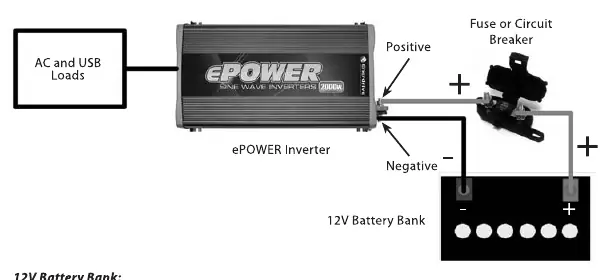
- The wiring diagram illustrates the connection from the battery bank, through the fuse/breaker and disconnect switch, to the inverter.
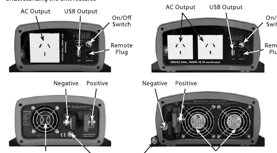
- The front panel diagram identifies the AC outlets, USB output, Power/Select button, and Remote plug.
- The rear panel diagram identifies the fan openings, ground terminal, and DC input terminals.
Model compatibility
- Not intended for use with life support systems or other medical equipment.
- Requires 12V DC input.
- Compatible with 230VAC appliances within the rated power limits.

Manual page author
David Miller
Documentation analyst
Organizes user manual content into clear summaries, with attention to model details, product context, and everyday usability.