Lighting / LED Modules
Installation Guide for ENTTEC Smart PXL 100x25 Dot
Comprehensive installation guide for the ENTTEC Smart PXL 100x25 Dot. Includes wiring diagrams, safety instructions, system planning, and maintenance procedures for 24V and 48V pixel dot systems.
Table of contents
Manual images
Click an image to enlargeQuick guide from the manual
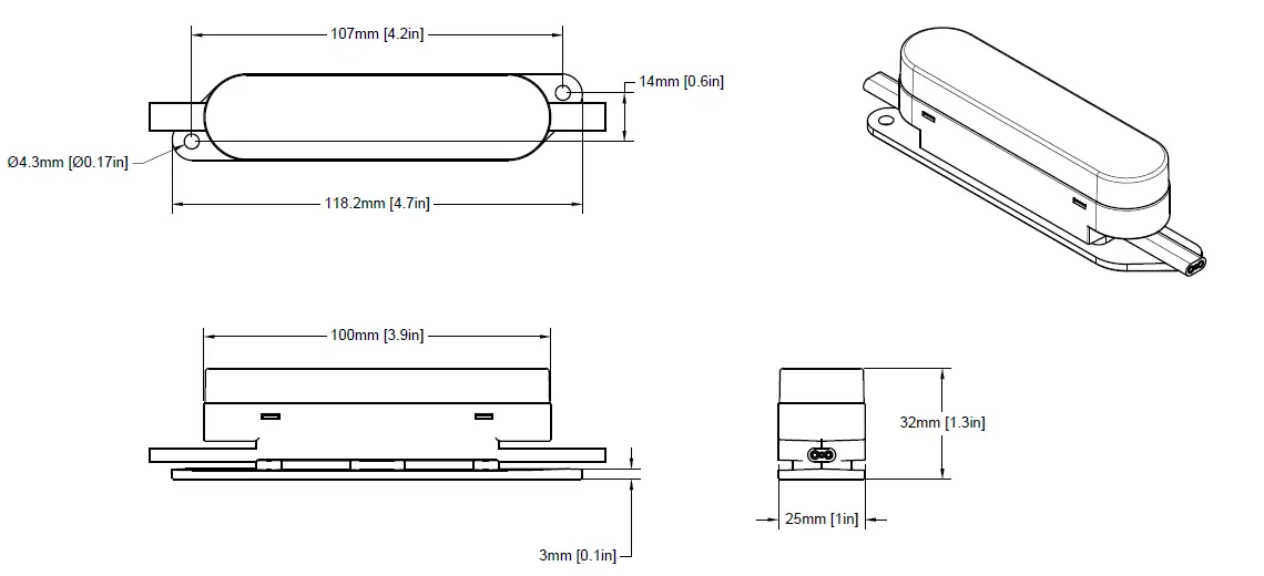
The ENTTEC Smart PXL 100x25 Dot is a high-resolution pixel dot system available in 24V and 48V variants. Before installation, ensure you have a complete system plan. Key requirements include maintaining correct data direction (indicated by arrows on the PCB), adhering to a maximum cable distance of 3000mm between devices, and ensuring power supplies are located as close as possible to the start of the chain to minimize voltage drop. Always use appropriate personal protective equipment and ensure the installation surface can support the weight of the system.
Key Electrical Safety
Installation must be performed by qualified personnel in accordance with local electrical codes. Key safety measures include:
- Isolate the installation from power immediately if any components show signs of damage, overheating, or moisture.
- Do not exceed the maximum number of dots or cable lengths specified.
- Do not hot swap strings or accessories.
- Ensure the system is powered down during cleaning or maintenance.
- Use an adequate RCBO on the mains power inlet.
- Do not bend cables beyond the specified minimum radius (30mm for dot cable, 68mm for accessory cable).
System Planning and Specification
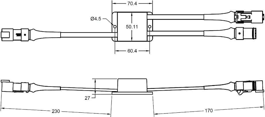
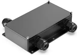
System design must respect limits regarding power draw, voltage drop, current throughput (10A max per string), and control channel availability. Significant voltage drop can cause brightness loss or color shifts. Use ENTTEC Power Injector accessories to inject power from additional PSUs if necessary, which removes voltage drop as a limiting factor for chain length.
Installation Guidelines
Always work with a plan that respects system limitations. When mounting:
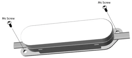
- Ensure no tension is exerted on cabling during tightening.
- Use suitable fasteners for the 4.3mm diameter mounting holes.
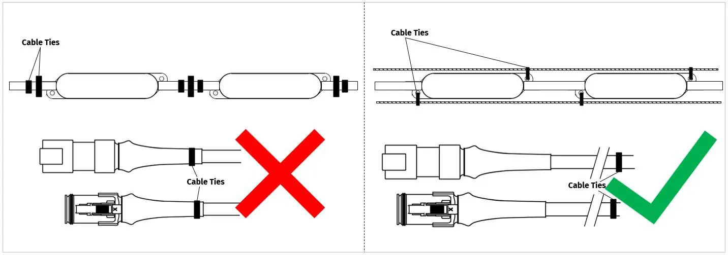
- For catenary mounting, use UV-resistant cable ties. Do not place ties directly on the cable leading in or out of the dot body to avoid strain.
- Mark hole positions accurately before drilling.
- Do not connect cabling until screws are fully tightened.
Wiring and Data
Data flows in one direction only, indicated by the arrow on the PCB. If the PCB is inaccessible, follow the ENTTEC logo orientation on the bottom of the housing. Each string uses 3 cores: Black (0V), White (Data), and Red (+V). Use cable ferrules for non-tinned cables. Always terminate the end of a chain with a Termination Plug (SKU 73015) to protect against short-circuiting and corrosion.
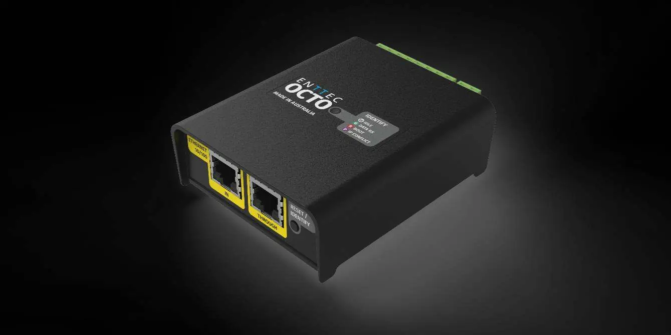
Control Systems
The system is compatible with ENTTEC OCTO and Pixelator systems. The OCTO converts pixel data from ArtNet, sACN, or KiNet. The Pixelator system uses PLink injectors to convert data locally. Do not mix controller types within a P-Link system to avoid content tearing.
Servicing and Cleaning
The system has no user-serviceable parts. If damaged, replace the component. For cleaning, power down the system. Use low-pressure compressed air to remove dust and dirt. Wipe with a damp microfiber cloth if necessary. Do not use abrasive, corrosive, or solvent-based cleaners, and do not use high-pressure water jets.
Practical help
Common problems
Brightness loss or color shift
This is likely caused by voltage drop. Reduce cable distance from the power source or use a Power Injector to add power from an additional PSU.
Dots not operating
Verify that data is flowing in the correct direction indicated by the arrow on the PCB. Ensure all connections are secure and not damaged.
Cable damage or short circuit
Ensure cables are not bent beyond the minimum radius (30mm for dot cable, 68mm for accessory cable) and are not under tension.
Overheating
Ensure sufficient airflow around the dots. Clean off dust and dirt buildup that may limit heat dissipation.
Before use
- Verify the operating voltage (24V or 48V) and ensure the power supply is appropriately fused.
- Check that all connectors are mated securely and show no signs of damage or corrosion.
- Ensure the installation surface can support the weight of the full string.
- Confirm data direction arrows are pointing in the correct flow direction.
- Ensure all exposed connectors are fitted with a Termination Plug (SKU 73015).
- Check that cable run lengths do not exceed 3000mm between devices.
Specs in practice
- Max cable distance
- 3000mm between S-PXL data source and string, or between string interconnects.
- Current throughput limit
- 10A maximum per string.
- DMX Channel Footprint
- RGB dots consume 6 channels; RGBW dots consume 8 channels.
- Operating Temperature
- Do not operate if ambient temperature exceeds 50°C (122°F).
Images and diagrams
- Wiring diagrams show the connection sequence from the controller to the PSU, Power Injector, and the string of dots.
- The Cable Core Identification Chart specifies pinouts for 24V and 48V systems (Black=0V, White=Data, Red=+V).
- Catenary mounting diagrams illustrate correct cable tie placement to avoid strain on the dot body.
Model compatibility
- Compatible with ENTTEC OCTO and Pixelator control systems.
- Requires PLink injectors when using the Pixelator system.
- All accessories use Amphenol AT series connectors.

Manual page author
David Miller
Documentation analyst
Organizes user manual content into clear summaries, with attention to model details, product context, and everyday usability.