Home / Electrical Accessories
Simon 82 LED Indicator 75802-31
Quick guide for the Simon 82 LED indicator module (75802-31). Includes installation instructions, wiring diagrams, and technical specifications for 127V~ systems.
Table of contents
Manual images
Click an image to enlargeQuick guide from the manual
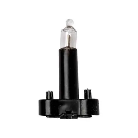
The Simon 82 LED indicator (Ref. 75802-31) is designed to add a luminous function to standard switches within the Simon 82 series. It is suitable for both surface and flush mounting in universal electrical boxes. Ensure your electrical system operates at 127V~ before installation.
Product description
This LED indicator is manufactured with a metal alloy (copper, zinc, lead, and brass) to ensure durability and safety. It is designed to withstand temperatures up to 50°C. The unit is compact, occupying 1 module, and is intended for use with Simon 82 plates and keys.
Technical specifications
- Voltage: 127V~
- Intensity: 1 mA
- Operating Temperature: Up to 50°C
- Compatibility: Simon 82 series plates and keys
- Installation Type: Surface or flush mount
- Cable Section: 3.3 mm
- Cable Stripping: 11 mm
Installation and wiring
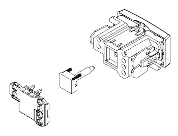
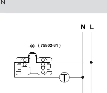
The installation process involves inserting the LED module into the switch mechanism. The device is compatible with universal flush-mounting boxes. When wiring, ensure the connection follows the provided diagram, connecting the indicator to the Line (L) and Neutral (N) terminals as required for the specific switch configuration.
Maintenance
The product is designed for a long service life and requires minimal maintenance. Ensure that the installation environment does not exceed the maximum operating temperature of 50°C.
Manufacturer information
Simon
Practical help
Before use
- Verify that the electrical system is 127V~.
- Ensure the switch mechanism is part of the Simon 82 series.
- Check that the installation box is a universal type.
- Prepare the cable by stripping 11 mm of insulation.
- Ensure the cable section is 3.3 mm.
Specs in practice
- Max Temperature
- 50°C (Maximum ambient temperature for safe operation).
Images and diagrams
- The assembly diagram illustrates how the LED module inserts into the switch mechanism.
- The wiring diagram shows the connection points for Line (L) and Neutral (N).
Model compatibility
- Compatible exclusively with Simon 82 series plates and keys.

Manual page author
Emily Carter
User documentation editor
Prepares concise manual descriptions and highlights the most useful setup, operation, and maintenance information for readers.