HVAC / HVAC Systems
Installation Instructions for Everwell 18K-60K Split System Heat Pump and Air Conditioner
Comprehensive installation guide for Everwell 18K-60K split system heat pumps and air conditioners. Includes detailed procedures for unit placement, refrigerant piping, electrical wiring, vacuum drying, and system troubleshooting.
Quick answers from the manual
Quick answer
- This manual provides installation, wiring, and maintenance procedures for Everwell 18K-60K split system heat pumps and air conditioners. It includes technical specifications, clearance requirements, and a troubleshooting guide based on LED flash codes. p. 1, 3, 23
Key actions
- Perform vacuum drying to eliminate moisture and air before charging refrigerant. p. 17
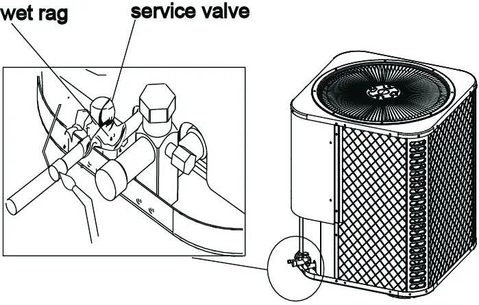
- Protect service valves with a wet rag during brazing to prevent heat damage. p. 16
First start
- Ensure all installation steps are complete, then set the unit to 'COOLING' mode via the remote controller to check for proper operation. p. 22
Problems and fixes
Green light flashes 2 times every 8 seconds
(T3) Temperature sensor fault
p. 23
Green light flashes 6 times every 8 seconds
Low pressure alarm
p. 23Error codes
| Code | Meaning | Action | Pages |
|---|---|---|---|
| Green light flashes 2 times | (T3) Temperature sensor fault | Check sensor | p. 23 |
| Green light flashes 6 times | Low pressure alarm | Check system pressure | p. 23 |
Technical specifications
| Parameter | Value | Meaning | Pages |
|---|---|---|---|
| Voltage | 208/230V | Rated power supply voltage | p. 8 |
| Frequency | 60Hz | Operating frequency | p. 8 |
Where to find it in the PDF
- Dimensions p. 3
- Wiring Diagrams p. 6, 7
- Trouble Code Table p. 23
Table of contents
Manual images
Click an image to enlargeQuick guide from the manual
This document provides installation and setup instructions for Everwell split system heat pumps and air conditioners ranging from 18K to 60K BTU. The manual is intended for qualified, licensed service personnel. Key requirements include proper structural support for the unit, adherence to clearance distances for airflow, and correct electrical and refrigerant connections. Always ensure the system is grounded and that all local electrical and safety regulations are followed.
Installation requirements
Before installation, ensure the chosen location can support the unit's weight and allows for proper maintenance access. The unit must be installed on a flat, horizontal surface. For ground installations, ensure the base is solid and will not shift. For roof installations, the structure must support the total weight of the unit, including any necessary mounting frames to minimize vibration transmission.
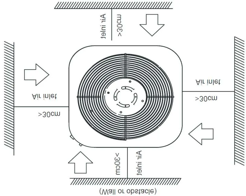
Clearance requirements
- Air Discharge: Maintain at least 60 inches of clearance above the unit.
- Service Access: Maintain at least 24 inches of clearance for service access.
- Multiple Units: If installing multiple units, space them a minimum of 18 inches apart (coil face to coil face).
Refrigerant piping
The system uses R410A refrigerant. When connecting pipes, ensure the section is flat and smooth after cutting. Use a phosphorous-copper alloy material for brazing; do not use soft solder. Always supply dry nitrogen through the tubing while brazing to prevent oxidation. Protect the service valve by wrapping it with a wet rag during the brazing process.
Vacuum drying
Vacuum drying is essential to eliminate moisture and non-condensable gases. Use a vacuum pump capable of reaching -755mmHg or above. If the vacuum level cannot be maintained after 1 hour, check for leaks.
Electrical wiring
All wiring must be performed by a qualified electrician. Ensure the power supply voltage matches the unit's specifications. Do not connect power wires to signal wire terminals. If power and signal wires run parallel, maintain a minimum gap of 300mm. Ensure the color coding of wires matches between the outdoor and indoor units.
Test operation
After installation, perform a test run. Verify that the indoor and outdoor units are installed properly, the refrigerant system is leak-checked, and the drainage is unimpeded. Set the unit to 'COOLING' mode via the remote controller and check for abnormal noise, vibration, or refrigerant leaks.
Troubleshooting
The system indicates faults via flashing green lights on the unit. Refer to the trouble code table in the manual to identify specific issues such as temperature sensor faults, high/low pressure alarms, or high exhaust temperature protection.
Practical help
Common problems
Green light flashes 2 times every 8 seconds
T3 Temperature sensor fault.
Green light flashes 6 times every 8 seconds
Low pressure alarm.
Green light flashes 1 time every 8 seconds
High pressure alarm.
Green light flashes 5 times every 8 seconds
High exhaust temperature protection.
Before use
- Ensure the installation location supports the unit's weight.
- Verify refrigerant pipe length and height drop are within specified limits.
- Confirm all electrical wiring is performed by a qualified electrician.
- Ensure the unit is grounded according to local regulations.
- Check that gas-side and liquid-side stop valves are open.
- Verify the power voltage fits the rated voltage of the air conditioner.
Images and diagrams
- Clearance diagrams show minimum distances from walls and obstacles to ensure proper airflow.
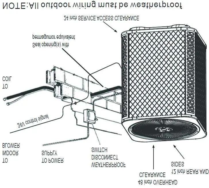
- Wiring diagrams illustrate the electrical connections between the outdoor unit and the thermostat.
- Brazing diagram demonstrates protecting the service valve with a wet rag to prevent heat damage.
Model compatibility
- The manual covers models 18K, 24K, 30K, 36K, 42K, 48K, and 60K.
- Ensure the indoor unit and outdoor unit are compatible for the specific system type (cooling only vs. cooling & heating).

Manual page author
David Miller
Documentation analyst
Organizes user manual content into clear summaries, with attention to model details, product context, and everyday usability.