HVAC / Parts & Accessories
Trane VRF Installer Training Manual
Comprehensive installer training guide for Trane VRF systems, covering refrigerant piping, MCU/EEV installation, addressing, system startup, commissioning, and troubleshooting error codes.
Quick answers from the manual
Quick answer
- This manual provides comprehensive installation, commissioning, and troubleshooting procedures for Trane VRF systems, including piping, wiring, addressing, and error code definitions. p. 1, 4, 167
Key actions
- Perform nitrogen purge during brazing p. 26
- Set MCU and ODU addresses p. 119, 120
First start
- Power up outdoor unit to initialize tracking p. 129
Problems and fixes
E108
Duplicate addresses; match port addresses all at once.
p. 131Maintenance and reset
- Discharge capacitors before working in control box p. 143
Technical specifications
| Parameter | Value | Meaning | Pages |
|---|---|---|---|
| Nitrogen flow rate | 1.76 ft³/hr | Required during brazing | p. 26 |
Where to find it in the PDF
- MCU & EEV p. 60, 71
- Addressing p. 118, 125
- Error Codes p. 143, 155, 167, 174
Table of contents
Manual images
Click an image to enlargeQuick guide from the manual
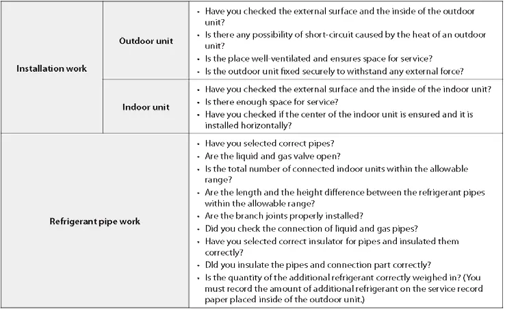
This manual serves as a comprehensive training guide for installing and commissioning Trane VRF systems. Key installation requirements include proper refrigerant piping techniques, correct MCU and EEV kit installation, and precise system addressing. Installers must follow the 99-step checklist provided in the appendices to ensure system integrity and qualify for the Trane warranty.
Piping Installation
Refrigerant piping must be ACR, clean, and capped. Nitrogen purging is mandatory during the entire brazing process to prevent oxidation. Adjust the nitrogen flow rate to 1.76 ft³/hr. All refrigerant pipes must be insulated with a minimum 1/2" wall thickness. Condensate drain pipes must be installed with a 1/100 slope and supported every 3-5 feet.


MCU & EEV Installation
Mode Control Units (MCU) should be installed in unoccupied areas to minimize noise. Ensure MCUs and EEV kits are installed level. Unused MCU outlet ports must be sealed against leaks and insulated. When connecting refrigerant pipes to IDUs, use the specified torque settings based on pipe diameter.
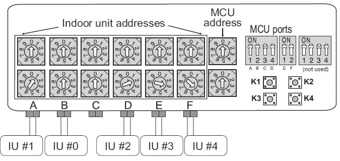
Addressing
System addressing is critical for proper operation. Rotary switches are used on the MCU for port addressing, while DIP switches on the Outdoor Unit (ODU) designate the Main/Sub units. Do not change addresses one at a time with the Technician Utility Tool (TUT) to avoid duplicate address errors (E108). Match port addresses all at once.
System Startup & Commissioning
Power up the outdoor unit to initialize tracking. Use the K1 button to initiate Auto Commissioning mode. The system must be commissioned and a report generated using the Technician Utility Tool (TUT) to qualify for the extended warranty. Ensure all piping and wiring are verified against the design plans before startup.
Troubleshooting
The manual includes an extensive list of error codes. Before checking the control box, turn off power and wait 15 minutes for capacitors to discharge, or discharge them by pressing the K2 button six times. Common errors like E108 (duplicate address) or E201 (communication error) are addressed through proper addressing and wiring checks.
Practical help
Common problems
Bubbling noise in MCU
Isolate MCU from occupied spaces using building layout or soundproofing materials.
E108 error code
Duplicate addresses; do not change addresses one at a time with TUT. Match port addresses all at once.
E201 error
Communication error between IDU and ODU; check installation quantity switch and reset tracking.
E573 error
HP & HR settings mismatch between WCUs in module installation.
Before use
- Obtain VRF Select Report
- Verify piping diameter and length
- Ensure nitrogen purge during brazing
- Check insulation thickness (1/2" min)
- Verify addressing settings on MCU and ODU
Specs in practice
- Nitrogen flow rate
- 1.76 ft³/hr during brazing to prevent oxidation.
- Insulation thickness
- 1/2" minimum wall thickness for refrigerant pipes.
- Combination Ratio
- Acceptable range 50% - 130% of ODU capacity.
Images and diagrams
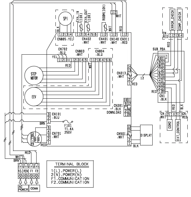
- Piping diagrams for ODU/WCU/IDU connections
- Wiring diagrams for communication and power
- MCU port addressing diagrams
- Error code display sequences
Model compatibility
- WCU requires water source (cooling tower/boiler)
- Heat Recovery systems require MCU
- Mini VRF connects up to 9 indoor units

Manual page author
Emily Carter
User documentation editor
Prepares concise manual descriptions and highlights the most useful setup, operation, and maintenance information for readers.