HVAC / Thermostats & Controls
Supplemental Instructions for Carrier 14SEERYAC-01SUP Air Conditioner and Gas Furnace System
Quick guide for checking inlet gas pressure and adjusting gas input on the Carrier 14SEERYAC-01SUP air conditioner and gas furnace system. Includes pressure specifications, safety warnings, and step-by-step procedures.
Table of contents
Manual images
Click an image to enlargeImportant Information
This document provides supplemental instructions for the Carrier 14SEERYAC-01SUP Single-Packaged Air Conditioner and Gas Furnace System. It specifically covers gas valve substitution, checking inlet gas pressure, and adjusting gas input. This unit is designed for Natural Gas only. If you intend to use LP/Propane, you must contact a distributor for a replacement gas valve and conversion kit.
Safety Warnings
FIRE HAZARD: Failure to follow safety instructions can result in personal injury, death, or property damage. Always ensure the inlet pressure tap set screw is tightened and the 1/8-in. NPT pipe plug is installed to prevent gas leaks.
Checking Inlet Gas Pressure
The inlet gas pressure must be checked while the furnace is operating in gas heat mode to ensure it does not fall below the minimum pressure specified on the rating plate.
- Turn off gas supply to the furnace and the electric switch on the gas valve.
- Loosen the set screw on the inlet tower pressure tap (max one full turn) using a 3/32-in. hex wrench.
- Connect a manometer to the inlet pressure tap using a 5/16” hose.
- Turn on the furnace power supply and the gas supply manual shutoff valve.
- Turn the furnace gas valve switch to the ON position.
- Jumper the R and W thermostat connections at the furnace control board.
- Once main burners ignite, confirm the inlet gas pressure is within the range specified on the rating plate.
- Remove the jumper to terminate the call for heat and wait for the blower off delay to complete.
- Turn off the furnace power supply and gas supply.
- Remove the manometer and hose, then tighten the set screw.
Adjusting Gas Input
Gas input is determined by measuring gas flow at the meter or by measuring manifold pressure. Measuring at the meter is recommended for natural gas units.
To measure manifold pressure:
- Turn off the gas supply.
- Remove the pipe plug on the manifold and screw in a 1/8” NPT brass hose barb, or loosen the set screw on the manifold tower pressure tap.
- Connect the manometer.
- Turn on the gas supply and record the gas meter test dial revolution time.
- Calculate the gas flow per hour and compare with the heating input table.
- If adjustment is needed, remove the regulator cover screw and turn the plastic adjustment screw (clockwise to increase, counterclockwise to decrease).
- Ensure manifold pressure is maintained between 3.2 and 3.8 IN. W.C.
- Replace the regulator cover screw, turn off gas, remove the manometer, and tighten the set screw.
Manufacturer information
Carrier Global Corporation
Practical help
Common problems
Gas pressure below minimum
Check supply pressure against the rating plate specifications while the furnace is operating in gas heat mode.
Gas leaks
Ensure the inlet pressure tap set screw is tightened and the 1/8-in. NPT pipe plug is properly installed.
Before use
- Ensure the unit is set for Natural Gas (not for propane without a conversion kit).
- Have a 3/32-in. hex wrench available.
- Have a manometer with a 5/16" hose ready.
- Turn off all other appliances using the same gas meter before measuring gas flow.
- Verify the heating input (BTUH) of your specific unit.
Specs in practice
- Manifold Pressure (Natural Gas)
- Must be maintained between 3.2 and 3.8 IN. W.C.
- Heating Input
- Ranges from 40,000 to 130,000 BTUH depending on the model configuration.
Images and diagrams
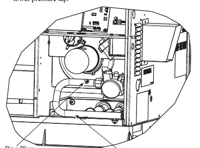
- Fig 1 shows the Burner Assembly and the location of the manifold pipe plug.
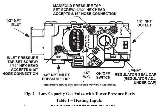
- Fig 2 details the Low Capacity Gas Valve, identifying the inlet pressure tap, manifold pressure tap, and the plastic adjustment screw.
Model compatibility
- Unit is for Natural Gas only.
- Requires a separate natural-to-propane conversion kit for LP/Propane use.

Manual page author
David Miller
Documentation analyst
Organizes user manual content into clear summaries, with attention to model details, product context, and everyday usability.