HVAC / HVAC Systems
User Manual for Carrier AquaEdge 19MV Liquid Chiller
Comprehensive start-up, operation, and maintenance guide for the Carrier AquaEdge 19MV liquid chiller. Includes safety procedures, refrigeration cycle details, start-up sequences, and troubleshooting.
Quick answers from the manual
Quick answer
- The 19MV is a high-efficiency centrifugal liquid chiller. This manual covers start-up, operation, maintenance, and troubleshooting for the unit, including its PIC6 control system and refrigeration cycle. p. 1, 20, 38
Key actions
- Perform pre-start checks and verify all alarms are cleared before starting. p. 20, 36
- Monitor refrigerant moisture indicator for single-phase flow and dry condition. p. 38
First start
- Verify power, cooling tower water levels, refrigerant valves, and water circuit flow before initial start-up. p. 36
Problems and fixes
Phase rotation alarm
Reverse any 2 of the 3 incoming power leads to the starter.
p. 38Maintenance and reset
- Reset After Service Hours to zero after major service work. p. 45
Technical specifications
| Parameter | Value | Meaning | Pages |
|---|---|---|---|
| Oil Charge (19MV Oiled) | 6.08 gal (23 L) | Required oil charge for the compressor. | p. 17 |
Where to find it in the PDF
- Safety Considerations p. 2, 3
- Start-Up/Shutdown Sequence p. 20, 22
- Maintenance p. 43, 45, 60
Table of contents
Manual images
Click an image to enlargeQuick guide from the manual
This document provides essential instructions for the start-up, operation, and maintenance of the Carrier AquaEdge 19MV liquid chiller. It is intended for trained and qualified service personnel. Always ensure all safety precautions are followed before performing any work on the unit.
Safety Considerations
Installation and servicing of air-conditioning equipment can be hazardous due to system pressure and electrical components. Always follow safety codes, wear appropriate personal protective equipment (safety glasses, work gloves), and ensure the unit is de-energized before servicing. Be aware of DANGER, WARNING, and CAUTION notices throughout the manual.
Chiller Familiarization
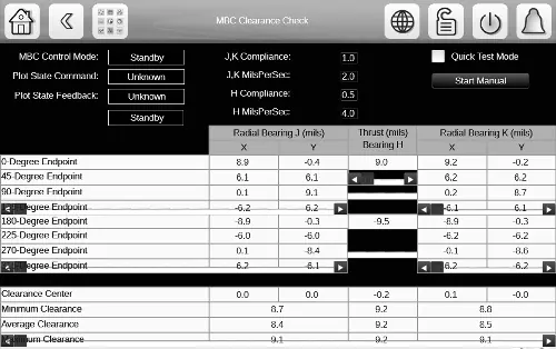
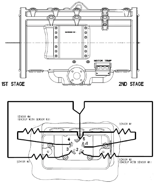
The 19MV chiller consists of several key components, including the evaporator, condenser, motor-compressor, VFD (Variable Frequency Drive), PIC6 Touch Screen HMI, and Magnetic Bearing Controller (MBC). The unit uses a microprocessor-based control system to match cooling capacity to the load.
Start-Up and Operation
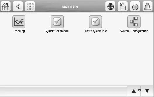
Before initial start-up, ensure all job data is available, the unit is free of shipping damage, and all gasketed joints are tightened. The start-up sequence involves pre-start checks, verification of water flow, and compressor levitation. The HMI provides the interface for starting, stopping, and monitoring the chiller. The unit can be operated in Local, Network, or Remote modes.
Maintenance
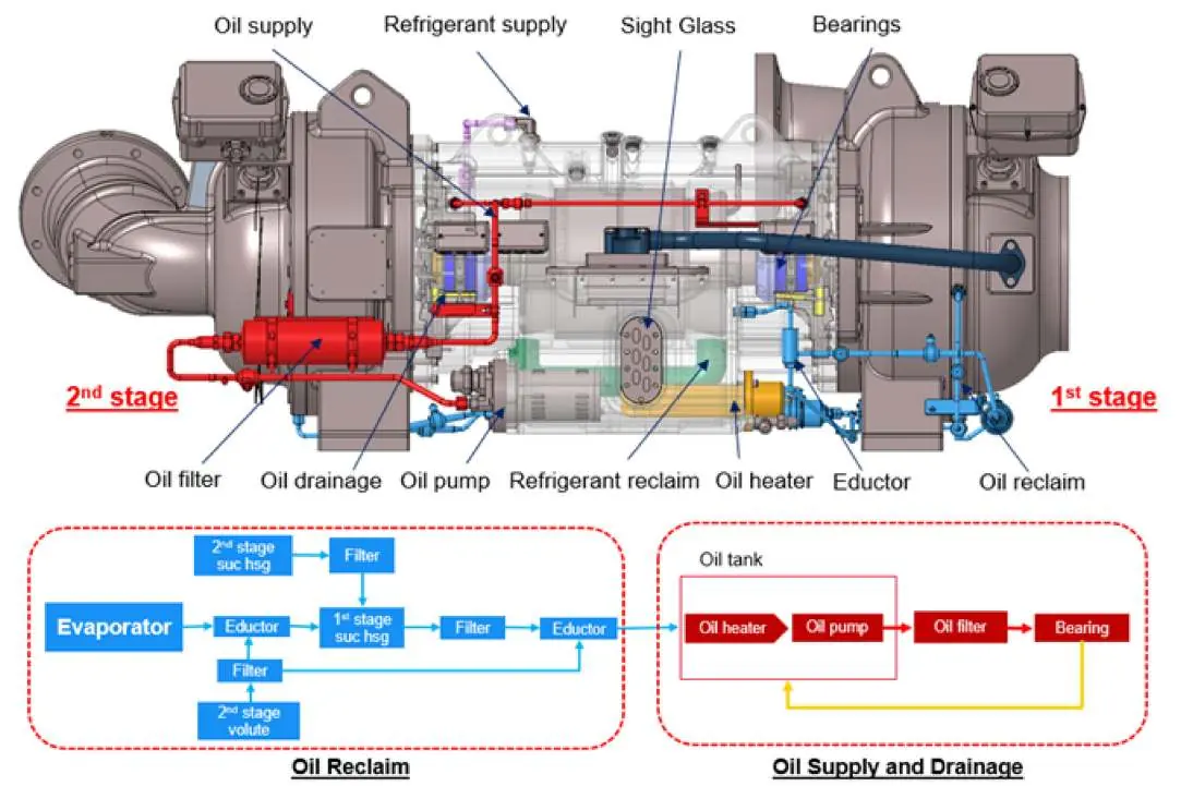
Scheduled maintenance is critical for reliable operation. This includes inspecting the power panel, changing refrigerant filters, inspecting safety relief devices, and performing compressor bearing maintenance. For oiled compressors, monitor oil levels and perform oil changes as required. Always ensure the chiller is properly dehydrated after any service that opens the refrigerant circuit.
Troubleshooting
The PIC6 control system includes diagnostic features to help identify and resolve issues. Check the HMI display for alarm messages. Temperature sensors can be checked by measuring resistance or voltage drop. If ground faults occur, follow the specific troubleshooting procedures provided in the manual.
Manufacturer information
Carrier Global Corporation
Practical help
Common problems
Chiller fails to start
Check for active alarms, ensure start-to-start/stop-to-start timers have elapsed, and verify all prestart conditions are met.
Incorrect phase rotation
Reverse any 2 of the 3 incoming power leads to the starter.
Low oil pressure (oiled compressors)
Check oil level, ensure oil pump is functioning, and check for oil foam caused by rapid guide vane opening.
Refrigerant leak
Use an electronic leak detector or soap bubble solution to locate the leak; repair and retest.
Before use
- Verify power is on to VFD, control panel, and pumps.
- Ensure cooling tower water is at proper level and temperature.
- Confirm all refrigerant valves are in correct operating positions.
- Verify water circuit valves are open and flow is as per design.
- Inspect the unit for any shipping or installation damage.
Images and diagrams
- Fig 2-5: Component layouts for different 19MV models.
- Fig 9-12: Refrigeration cycle diagrams for various configurations.
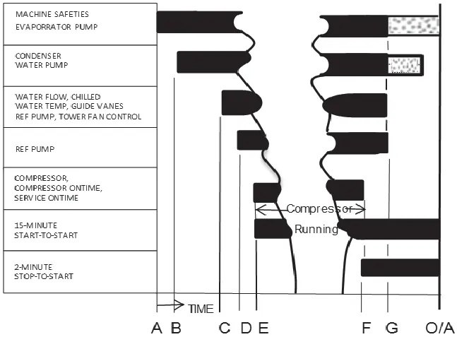
- Fig 19-20: Control timing sequences for start-up.
- Fig 45-46: Guide vane actuator details.
Model compatibility
- Compatible with R-513A, R-515B, and R-1234ze(E) refrigerants.
- Requires specific water treatment to prevent corrosion and scaling.

Manual page author
David Miller
Documentation analyst
Organizes user manual content into clear summaries, with attention to model details, product context, and everyday usability.