Electronics / Speakers Soundbars
Fender American Ultra Telecaster (011803XXXX) Parts and Specifications Guide
A comprehensive technical guide for the Fender American Ultra Telecaster, featuring detailed parts diagrams, wiring schematics, switch control functions, and precise hardware specifications.
Table of contents
Quick guide from the manual
This document serves as the official parts and technical reference for the Fender American Ultra Telecaster (011803XXXX). It provides detailed diagrams for component identification, wiring schematics, and specific hardware measurements required for maintenance and setup.
Parts Layout
The guitar features a modular design with specific components for the body, neck, and electronics. Key components include the Ultra Tele neck assembly, locking 'F' tuners, N4 vintage-style pickups, and the S-1 switching system. Refer to the parts list for specific part numbers when ordering replacements.
Wiring Assembly
The wiring assembly utilizes a 3-way pickup switch and a S-1 switch integrated into the volume control. The circuit includes a treble bleed PCB to maintain high-frequency clarity when rolling back the volume, and a .022µF capacitor for tone control. The bridge pickup is grounded via a black wire to the bridge plate, and the body is grounded via a dedicated lug.
Switch and Control Function
The guitar features a 3-way switch and an S-1 switch that modifies the pickup configuration:
- 3-Way Switch: Standard selection between neck, bridge, or both pickups.
- S-1 Switch: Functions only in position #2 (both pickups). In the UP position, pickups are connected in parallel. In the DOWN position, pickups are connected in series for a thicker, higher-output tone.
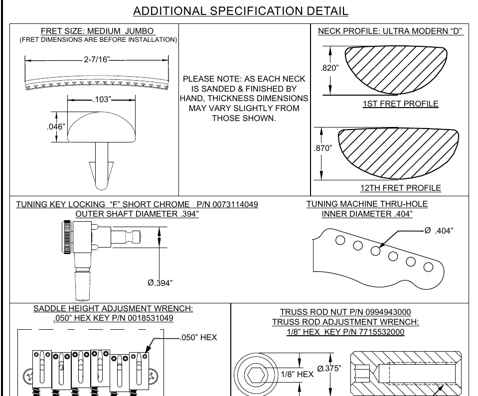
Additional Specification Detail
Technical specifications for setup and maintenance include:
- Neck Profile: Ultra Modern 'D' shape.
- Fret Size: Medium Jumbo.
- Pickup Specs: Alnico 5 unbeveled magnets; Neck DC resistance 11.3-11.7kΩ, Bridge DC resistance 9.9-10.5kΩ.
- Hardware: Locking 'F' tuners (0.394" shaft diameter), 1/8" hex key for truss rod, and 0.050" hex key for saddle height adjustment.
Manufacturer information
Fender Musical Instruments Corporation
Practical help
Common problems
S-1 switch does not seem to change the sound.
The S-1 switch only functions when the 3-way pickup selector is in position #2 (middle position).
Difficulty adjusting saddle height.
Ensure you are using the correct 0.050" hex key provided for the saddle height set screws.
Before use
- Verify the 3-way switch position for desired pickup selection.
- Check S-1 switch status (Up/Down) to toggle between parallel and series wiring in position #2.
- Ensure the truss rod is adjusted using a 1/8" hex key if neck relief is incorrect.
- Confirm saddle height using the 0.050" hex key.
Specs in practice
- Neck Profile: Ultra Modern 'D'
- The specific ergonomic shape of the neck, measuring 0.820" at the 1st fret and 0.870" at the 12th fret.
- Treble Bleed PCB
- An electronic component that prevents the loss of high frequencies when the volume knob is turned down.
- DC Resistance
- Indicates the output level of the pickups; higher values (Neck: 11.3-11.7kΩ) generally indicate higher output.
Images and diagrams
- The Parts Layout diagram identifies 44 distinct components including body, neck, and hardware.
- The Wiring Assembly diagram shows the signal path from pickups through the S-1 switch and tone control.
- The Switch and Control Function chart illustrates the specific pickup combinations available via the 3-way and S-1 switches.
Model compatibility
- Neck thickness dimensions may vary slightly due to hand-sanding and finishing processes.
- Fret dimensions provided are measurements taken before installation.

Manual page author
Emily Carter
User documentation editor
Prepares concise manual descriptions and highlights the most useful setup, operation, and maintenance information for readers.