Home / Security
FortiGate 1000F Series QuickStart Guide
Essential setup, installation, and configuration guide for the FortiGate 1000F and 1001F series security appliances.
Table of contents
Manual images
Jump to the sectionProduct Overview
The FortiGate 1000F series, including models FG-1000F and FG-1001F, provides high-performance network security. This guide covers the initial setup, hardware installation, and basic configuration required to get your device operational within your network environment.
Before You Begin
Before starting the installation, it is recommended to register your device at the Fortinet support portal. Registration provides access to critical FortiGuard updates, cloud management features, firmware upgrades, technical support, and warranty coverage. You can also utilize the FortiExplorer app on your mobile device for rapid provisioning and deployment of Security Fabric components.
Package Contents
Ensure your package includes the FortiGate device, a QuickStart guide, two power cables, an Ethernet cable, a console cable, four rubber feet, two SFP transceivers, two rack-mount brackets, and eight bracket screws. DC models also include two grounding lugs and six terminal rings.
Hardware Installation
The device can be installed on a desktop or mounted in a rack. For desktop use, place the unit on a flat, clean, and stable surface, ensuring at least 1.5 inches of clearance on all sides for proper airflow. For rack mounting, it is recommended that two or more people perform the installation to avoid personal injury or equipment damage. Ensure the rack environment is well-ventilated and that the device is properly grounded.
Initial Setup
You can configure the device using the GUI or the CLI. For GUI access, connect your management computer to the MGMT port using an Ethernet cable. Configure your computer with an IP address in the 192.168.1.x range and a subnet mask of 255.255.255.0. Access the device via a web browser at https://192.168.1.99 using the default username 'admin' and a blank password. For CLI access, connect a console cable to the console port and use terminal emulation software with settings: 9600 baud, 8 data bits, 1 stop bit, no parity, and no flow control.
Safety and Maintenance
Always operate the device within the specified ambient temperature range of 0°C to 40°C. Ensure that the airflow is not obstructed. The device must be connected to a properly wired earth ground. When handling SFP modules, ensure they are installed and removed correctly using the provided cage socket mechanisms. For DC models, ensure that cables are a minimum of 12 AWG and are securely fastened to the PSU terminals.

Manufacturer information
Fortinet, Inc.
Practical help
Common problems
Cannot access the web GUI
Ensure your management computer is set to an IP in the 192.168.1.x range with subnet 255.255.255.0 and that you are using the correct MGMT port.
Device not booting or showing major alarm
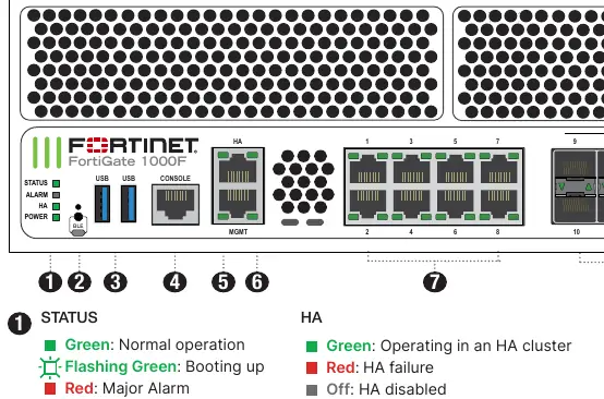
Check the status LEDs on the front panel. A red status light indicates a major alarm; consult the admin guide for troubleshooting steps.
SFP module not recognized
Ensure the SFP module is fully inserted into the cage socket and locked in place.
Before use
- Register the device at support.fortinet.com
- Verify all package contents are present
- Ensure a stable, flat surface or rack space is available
- Confirm power source matches device requirements (AC or DC)
- Prepare a management computer with an Ethernet port
- Download the FortiExplorer app if using mobile setup
- Ensure proper grounding is available for rack installation
Specs in practice
- Console Speed
- The default baud rate (9600) required for serial communication with the device CLI.
- Operating Temperature
- The safe ambient temperature range (0°C to 40°C) for device operation.
- DC Power Input
- The required DC voltage range (-48VDC to -60VDC) for DC-specific models.
Images and diagrams
- Front panel LEDs indicate status, alarm, HA, and power states.
- Port LEDs show link/activity and speed for RJ45, SFP+, SFP28, and QSFP28 ports.
- Rear panel shows power supply units and fan modules.
- SFP installation involves inserting the module into the cage socket until it clicks.
Model compatibility
- DC models require a minimum of 12 AWG cabling.
- SFP ports must use UL Listed Optional Transceiver products rated 3.3Vdc, Laser Class 1.
- All Ethernet cables are designed for intra-building connections only.

Manual page author
Michael Turner
Technical manual editor
Reviews PDF manuals for structure, safety notes, and practical product details so readers can find the right information quickly.