Lighting / Fixtures
User Manual for FOS Hydor 120W RGBL Lighting Fixture
Quick guide for the FOS Hydor 120W RGBL lighting fixture. Includes safety precautions, installation guidelines, DMX channel settings, maintenance tips, and technical specifications.
Table of contents
Manual images
Click an image to enlargeQuick Guide from the Manual
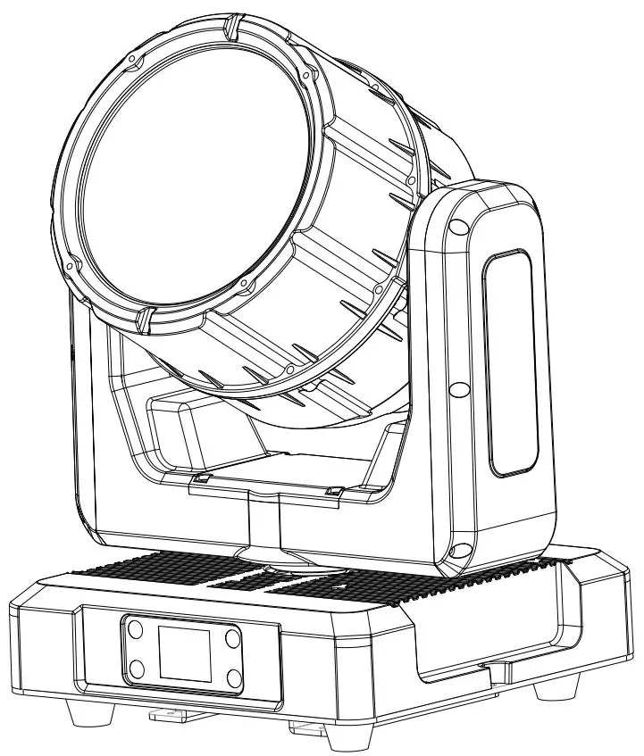
The FOS Hydor 120W RGBL is a professional stage lighting fixture. This manual provides essential safety, installation, and operational guidelines. Key points include ensuring proper grounding (Protection Class 1), maintaining a minimum distance of 1 meter from surfaces and 0.5 meters from flammable materials, and ensuring the fixture is installed by qualified personnel only.
Safety Precautions
- Grounding: The fixture must be properly grounded.
- Heat: Do not touch the housing during operation; allow 15 minutes to cool before servicing. External surfaces can reach 85°C (185°F).
- Environment: Keep at least 1 meter away from objects and 0.5 meters from flammable materials.
- Maintenance: No user-serviceable parts inside. Do not open the fixture while in use.
- Connections: Ensure all connections and end caps are sealed with dielectric grease to prevent corrosion.
Overview
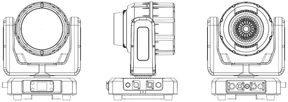
The fixture features an LCD display for the system menu, DMX input/output (3-pin and 5-pin), power input/output, and an antenna for wireless control. Refer to the overview diagram for the specific location of these ports.
Installation Guidelines
- Professional Installation: Only qualified personnel should install the fixture.
- Rigging: Use only original rigging parts. Always secure overhead installations with a secondary safety attachment (e.g., safety cable).
- Environment: Ambient operating temperature range is -20°C to 45°C (-4°F to 113°F).
- Ventilation: Do not block air ventilation slots; keep fans and inlets clean. Allow 15cm (6 inches) of clearance for cooling.
System Menu
The system menu allows configuration of the following:
- Control: DMX Address (001-512), Channel Mode (12CH/22CH), Signal Select (XLR/Wireless), and Manual control.
- Settings: Display settings, Key Lock, DMX Fault behavior (Hold/Blackout), Dimmer Speed, Dimmer Curve, LED Frequency, Fan Mode, and Calibration settings.
- Information: View error info, temperature, software version, and UID.
DMX Control
The fixture supports 12CH mode. Channels control Pan, Tilt, Zoom, Dimmer, Strobe effects, RGB color mixing, and color temperature presets (1800K-8000K). Refer to the DMX chart for specific channel values and functions.
Maintenance
- Cleaning: Clean the external lens surface periodically with a soft cloth. Never use alcohol, solvents, or ammonia-based cleaners.
- Routine Inspection: Have an approved electrical engineer perform a detailed electric check every three months. Ensure all screws and fasteners are tight and check for housing deformations.
Specifications
- Light Source: 120W RGBL LED.
- Output: 2500lm, 375,000 cd (narrow beam).
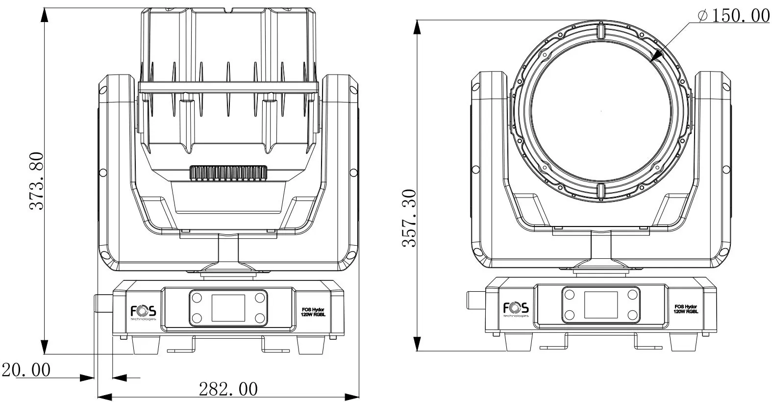
- Optics: 140mm Fresnel lens, 3.8° to 38° zoom.
- Electrical: 100-240V, 50/60Hz.
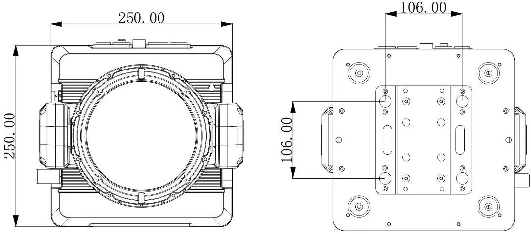
- Construction: 282 x 250 x 364.8 mm, 7 kg.
- IP Rating: IP65.
Practical help
Common problems
Light smoke or smell during initial operation
This is a normal process caused by excess paint in the interior of the casing burning off from the heat; it will decrease gradually.
Fixture not responding or DMX issues
Check the Signal Select setting in the menu (XLR vs Wireless) and ensure DMX cables are securely connected.
Overheating or fan issues
Ensure air ventilation slots are not blocked and fans are clean. Check Fan Mode settings in the menu.
Before use
- Verify the fixture is properly grounded (Protection Class 1).
- Ensure the ambient temperature is between -20°C and 45°C.
- Check that all power cords and connectors are undamaged.
- Ensure ventilation slots are clear of obstructions.
- Verify that the mounting structure is certified to hold the fixture's weight.
- Apply dielectric grease to connections if exposed to moisture.
Images and diagrams
- The overview diagram identifies the LCD display, DMX inputs/outputs (3-pin and 5-pin), power connections, and antenna.
- Dimensional drawings provide the exact footprint and height for mounting and clearance planning.
Model compatibility
- Supports both 3-pin and 5-pin waterproof XLR for data.
- Supports DMX and W-DMX (Wireless DMX) control.

Manual page author
David Miller
Documentation analyst
Organizes user manual content into clear summaries, with attention to model details, product context, and everyday usability.