Lighting / Fixtures
Installation Manual for Hudson Valley 1113-OB Granby Pendant Ceiling Light
Quick installation guide for the Hudson Valley 1113-OB Granby Pendant Ceiling Light. Includes wiring instructions, safety warnings, parts list, and assembly steps.
Table of contents
Important Safety Information
Before beginning installation, please read all instructions carefully. Failure to follow these guidelines may result in serious injury or death.
- Disconnect Power: Always turn off electricity at the breaker or fuse box before re-lamping or wiring the fixture.
- Professional Installation: Installation and maintenance should be performed by a licensed electrician or certified factory-trained technician.
- Compliance: The fixture must be installed in accordance with all applicable national and local electrical and building codes.
- California Prop 65: This product contains chemicals known to the State of California to cause cancer, birth defects, or other reproductive harm. Wash hands after handling.
Parts List
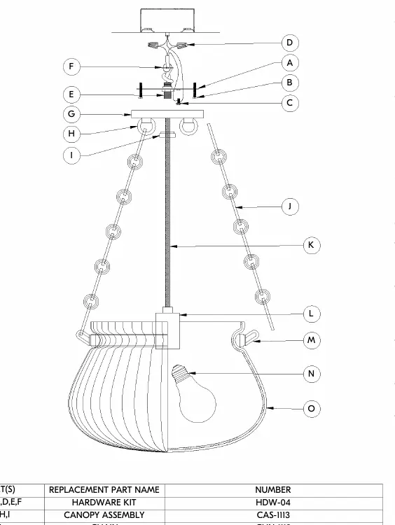
Before discarding the carton, ensure all parts are present. The hardware kit (HDW-04) includes the mounting plate, screws, and wire nuts. Other components include the canopy assembly, chain, ring, and glass shade.
Installation Steps
- Feed the fixture wire through the screw collar, canopy, nipple, mounting plate, and strain relief washer to your desired hanging height.
- Tie an overhand knot in the wire above the nipple to secure it. Trim excess wire, leaving at least 6 inches beyond the knot, and strip 5/8 inch of insulation from the ends.
- Attach the mounting plate to the junction box using the provided mounting screws. Ensure the junction box is securely mounted to the building structure.
- Install the bulb into the socket. Note: This fixture is rated for a maximum 15-watt Type A lamp. Do not exceed this wattage.
- Place the glass shade into the fixture ring.
- Open the end link of the chain and attach it to the loop on the ring. Hang the ring on the chain at the desired height and remove excess chain links.
- Feed the wire through the chain, loop, canopy, and mounting plate.
- Open the top link of the chain and hang the ring assembly to the loop.
- Cut excess wire and strip the insulation from the lead ends.
- Connect the ground wire (green or bare copper) to the ground wire in the junction box or the ground screw on the mounting plate.
- Connect the fixture lead with ridges to the neutral (white) wire in the outlet box using a wire nut. Wrap the connection with electrical tape to seal the fastener.
- Connect the smooth fixture lead to the hot (black) wire in the junction box using a wire nut. Secure with electrical tape.
- Push all wires back into the junction box, lift the canopy to the ceiling, and secure it with the screw collar onto the nipple.
- Restore power at the breaker or fuse box.
Maintenance
Clean the fixture using a soft, dry cloth only. Do not use any chemical cleansers or abrasive materials.
Practical help
Common problems
Fixture does not light up
Check that the bulb is installed correctly and does not exceed the 15W maximum rating. Verify all wiring connections are secure.
Short circuit or electrical hazard
Ensure there are no exposed wire strands at the connections. Use electrical tape to seal the wire nut connections properly.
Fixture is loose or unstable
Ensure the junction box is securely mounted to the building structure and the mounting plate is firmly attached.
Before use
- Disconnect power at the breaker or fuse box.
- Verify all parts are present using the parts list.
- Ensure the junction box is a standard round or octagon type.
- Have a licensed electrician available for installation.
- Check that the bulb wattage does not exceed 15W.
Specs in practice
- Max 15W Type A
- The maximum allowed wattage for the light bulb to prevent overheating.
- 5/8 inch strip
- The recommended length of insulation to remove from wire ends for proper connection.
Images and diagrams
- The assembly diagram illustrates the connection order from the ceiling junction box down to the glass shade.
- It identifies the hardware kit components (A-F) and the main fixture parts (G-O).
Model compatibility
- Designed for standard round or octagon junction boxes.

Manual page author
David Miller
Documentation analyst
Organizes user manual content into clear summaries, with attention to model details, product context, and everyday usability.