Lighting / Fixtures
Installation Manual for Hudson Valley Joan 1415-AGB Wall Sconce
Get started with your Hudson Valley Joan 1415-AGB wall sconce. This guide covers both hardwired and plug-in installation methods, safety precautions, wiring diagrams, and bulb requirements.
Table of contents
Manual images
Click an image to enlargeQuick guide from the manual
This document provides installation instructions for the Hudson Valley Joan 1415-AGB wall sconce. The fixture supports two installation types: hardwired (junction box) and plug-in. Always disconnect power before starting any electrical work. Installation should be performed by a licensed electrician or certified technician.
Safety warnings
- Disconnect power at the breaker or fuse box before re-lamping or wiring.
- This fixture contains chemicals known to the State of California to cause cancer and reproductive harm (Prop 65). Wash hands after handling.
- Do not exceed the maximum wattage of 15W for the Type A lamp.
- Ensure no exposed wire strands exist at connections to prevent short circuits.
Hardwired installation
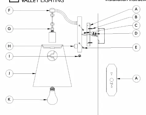
- Attach the mounting plate (A) to the junction box using mounting screws (B).
- Connect the ground wire (green) to the ground in the outlet box or the ground screw (C).
- Connect the white fixture lead to the neutral wire and the black fixture lead to the hot wire using wire nuts (D). Wrap connections with electrical tape.
- Attach the fixture assembly (F) to the mounting plate and secure with fixture mounting screws (E).
- Install the shade (J) and secure with the ring (G).
- Screw in the bulb (K) and restore power.
Plug-in installation
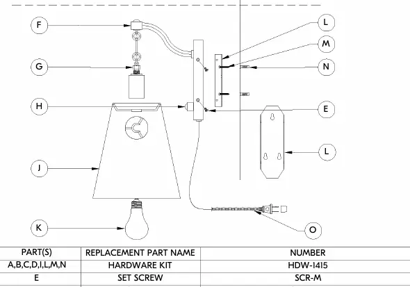
- Mark holes on the wall for wall anchors (N) and drill.
- Attach the mounting plate (L) to the wall using wood screws (M) and anchors.
- Attach the fixture assembly (F) to the mounting plate and secure with set screws (E).
- Install the shade (J) and secure with the ring (G).
- Screw in the bulb (K).
- Plug the cord (O) into the wall outlet.
Maintenance
Clean the fixture with a soft, dry cloth only. Do not use cleansers.
Practical help
Common problems
Fixture not turning on
Check if the bulb wattage exceeds 15W, ensure the switch is in the 'on' position, and verify power at the breaker.
Risk of short circuit
Ensure no exposed wire strands are visible at the wire nut connections; wrap connections with electrical tape.
Before use
- Disconnect power at the breaker.
- Verify junction box is securely mounted to the building structure.
- Ensure you have a Type A bulb (max 15W).
- Check that all parts listed in the manual are present.
- Wash hands after handling the fixture due to Prop 65 chemicals.
Specs in practice
- Max 15W Type A
- The maximum power rating for the bulb. Exceeding this may cause damage or fire.
Images and diagrams
- The wiring diagram illustrates the connection of Ground (Green), Neutral (White), and Hot (Black) wires using wire nuts.
- The parts diagram identifies the mounting plate, screws, shade, and bulb socket.
Model compatibility
- Designed for standard 2x3 junction boxes.

Manual page author
David Miller
Documentation analyst
Organizes user manual content into clear summaries, with attention to model details, product context, and everyday usability.