Home / Security
User Manual for Netvox R718NL1 Wireless Light Sensor and 1-Phase Current Meter
Quick start guide and user manual for the Netvox R718NL1 series. Learn how to install, configure, and maintain your wireless light sensor and 1-phase current meter, including wiring instructions and LoRaWAN setup.
Table of contents
Manual images
Click an image to enlargeQuick guide from the manual
The Netvox R718NL1 series is a wireless device combining a light sensor and a 1-phase current meter, designed for LoRaWAN Class A networks. This guide covers the essential setup, installation, and maintenance procedures for the device.
Appearance
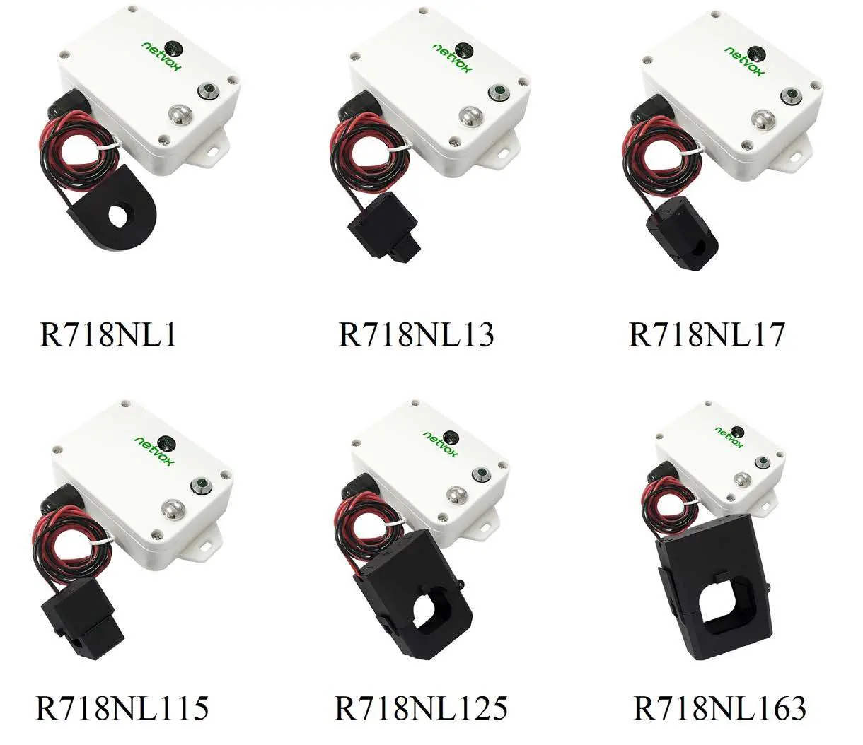
The device consists of a main body with a light sensor, indicator light, function key, and an external Current Transformer (CT). The series includes various models (R718NL1, R718NL13, R718NL17, R718NL115, R718NL125, R718NL163) with different CT measurement ranges.
Set up Instruction
Powering On/Off:
- Power on: Insert the two ER14505 3.6V Lithium AA batteries.
- Turn on: Press and hold the function key for 3 seconds until the green indicator flashes once.
- Turn off: Press and hold the function key for 5 seconds until the green indicator flashes 20 times.
- Power off: Remove the batteries.
Network Joining:
- Upon turning on, the device automatically searches for a network.
- If the device fails to join, it will wake up every 15 seconds for the first two minutes to send a join request, then every 15 minutes thereafter.
Installation
The device is waterproof and can be mounted using the built-in magnet on iron surfaces or fixed to a wall with screws. When installing the current transformer:
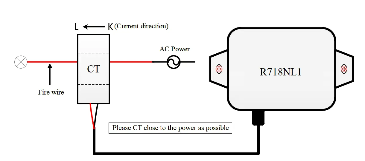
- Separate the live and neutral wires.
- Clamp the CT around the live wire only.
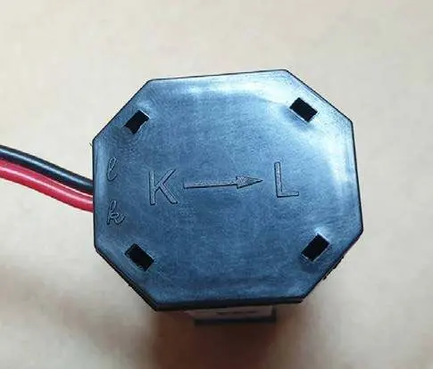
- Ensure the current direction is from K to L as marked on the CT.
- Do not clamp both live and neutral wires together, as they will offset each other and result in a measurement of 0.
- Avoid installing in metal shielded boxes or environments with strong electrical interference.
Data Report
The device reports data based on configured Min/Max intervals and reportable change thresholds. The default configuration is set to 30 minutes for both Min and Max intervals. If the current or illuminance change exceeds the set threshold, the device will report immediately at the Min Interval. Otherwise, it reports at the Max Interval.
Battery Passivation
If the device has been in storage for a long time, the lithium batteries may form a passivation layer, causing voltage delay. If the voltage is below 3.3V when tested with a 68ohm resistor, the battery requires activation. Connect the battery to a 68ohm resistor in parallel for 6-8 minutes to eliminate hysteresis.
Important Maintenance Instruction
- Keep the device dry to prevent corrosion of electronic circuits.
- Avoid dusty, dirty, or extreme temperature environments.
- Do not use strong chemicals or detergents for cleaning.
- Do not disassemble the device unless replacing batteries.
- When replacing batteries, ensure the waterproof gasket is not damaged and tighten screws to a torque of 4kgf if using an electric screwdriver.
Manufacturer information
Netvox Technology Co., Ltd.
Practical help
Common problems
Device fails to join the network
Check device verification information on the gateway or consult your platform server provider.
Measurement is 0
Ensure the live and neutral wires are separated. If both are clamped together, they will offset each other.
Battery passivation (device not working correctly)
Test battery voltage with a 68ohm resistor. If below 3.3V, connect to a 68ohm resistor in parallel for 6-8 minutes to activate.
Before use
- Check for physical deformation of the device.
- Confirm the load current is within the CT measurement range.
- Ensure the environment is free from strong magnetic fields.
- Verify batteries are installed correctly.
- Ensure the device is not installed in a metal shielded box.
Specs in practice
- Min Interval
- The minimum time between data reports; the device samples current 15 minutes before this interval.
- Max Interval
- The maximum time between data reports if no significant change is detected.
- Reportable Change
- The threshold for current or illuminance change that triggers an immediate report.
Images and diagrams
- The CT wiring diagram shows the correct orientation (K to L) and placement around the live wire only.
- The appearance diagram identifies the light sensor, indicator, function key, and CT.
Model compatibility
- Compatible with LoRaWAN Class A protocol.
- Requires 2x ER14505 3.6V Lithium AA batteries.
- Main body protection level: IP53; Sensor protection level: IP30.

Manual page author
Emily Carter
User documentation editor
Prepares concise manual descriptions and highlights the most useful setup, operation, and maintenance information for readers.