Smart Home / Smart Relays
User Manual for Shelly Wave PM Mini Smart Power Meter
Quick guide for the Shelly Wave PM Mini smart power meter. Learn about installation, Z-Wave network inclusion, LED signalization, and technical specifications.
Table of contents
Quick guide from the manual
The Shelly Wave PM Mini is a smart power meter designed for remote monitoring of electric appliances with a load of up to 16 A. It operates on the Z-Wave wireless protocol and requires a Z-Wave gateway for configuration and remote control. This device is intended for installation in standard electrical wall boxes.
Installation
Warning: Installation must be performed by a qualified electrician. Ensure there is no voltage present at the terminals before starting.
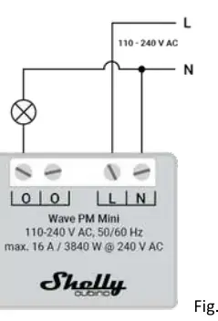
- Wiring: Connect the Neutral wire to the N terminal and the Live wire (110-240 V AC) to the L terminal. Connect the load to the O terminals.
- Safety: The load circuit must be secured by a cable protection switch (EN60898-1, tripping characteristic B or C, max 16 A). Do not connect SELV/PELV circuits to the inputs/outputs.
- Antenna: Do not shorten the antenna and place it away from metal elements to avoid signal interference.
Z-Wave Network Inclusion and Exclusion
The device supports SmartStart and manual inclusion via the S button.
- SmartStart: Scan the QR code on the device label with your gateway. Connect the device to power; it will be added automatically within 10 minutes.
- S Button Inclusion: Enable add/remove mode on your gateway. Press and hold the S button until the LED turns solid blue. Release and press/hold (>2s) until the blue LED blinks in Mode 3. Releasing starts the Learn mode.
- Exclusion: Follow the same procedure as S button inclusion while the gateway is in exclusion mode.
Factory Reset
Factory reset deletes all custom parameters and network settings.
- Enter Setting mode by pressing and holding the S button until the LED turns solid blue.
- Press the S button multiple times until the LED turns solid red.
- Press and hold (>2s) the S button until the red LED blinks in Mode 3.
- Release the button to start the reset. The LED will turn solid green for 1s, then blink blue and red.
LED Signalization
The device uses an RGB LED to indicate status:
- Normal Mode: Stable device function.
- Adding/Removing: Blinking blue in Mode 2.
- Added/Included: Blinking green in Mode 1.
- Overheat/Alarm: Blinking red in Mode 4.
- Checking Power Supply: Blinking blue and red in Mode 5.
Technical Specifications
- Power Supply: 110-240 V AC, 50/60 Hz
- Max Load: 16 A / 3840 W
- Operating Temperature: -20°C to 40°C
- Z-Wave Frequency: 868.4 MHz
- Dimensions: 29x35x16 mm
Practical help
Common problems
Device not added to Z-Wave network
Check if the blue LED is blinking in Mode 1. If so, the device is not added. Ensure the gateway is in inclusion mode.
Network congestion
Setting the power report interval (Parameter 39) to less than 30s can cause slow device response and network instability.
Overheat or Over-current detected
The device will switch off outputs. Restore operation via a power cycle or a short press on the S button.
Before use
- Ensure power is turned off at the breaker before installation.
- Verify the power supply is 110-240 V AC.
- Keep the PIN code (DSK) safe, as it is required for S2 inclusion.
- Ensure your Z-Wave gateway supports Security 2 (S2) for full functionality.
- Use solid single-core cables or stranded cables with ferrules.
Specs in practice
- Max. measurement power
- 3840 W (16 A load limit).
- External protection
- Requires a 16 A cable protection switch (tripping characteristic B or C).
- Ambient temperature
- Operating range is -20°C to 40°C.
Images and diagrams
- Fig 1: Wiring diagram showing connections for L (Live) and N (Neutral) terminals.
- Fig 2: Location of the S button on the device housing.
Model compatibility
- Requires a Security 2 (S2) enabled Z-Wave gateway to utilize all features.
- Compatible with resistive, inductive (with RC Snubber), and capacitive loads.

Manual page author
Emily Carter
User documentation editor
Prepares concise manual descriptions and highlights the most useful setup, operation, and maintenance information for readers.