Automotive / Electrical Accessories
Nilight 10038W LED Light Bar Wiring Harness Kit User Manual
Quick guide for the Nilight 10038W LED Light Bar Wiring Harness Kit. Includes installation steps, 5-pin rocker switch wiring methods (Method A and B), pin-tab configurations, and power specifications.
Table of contents
Quick guide from the manual
This document provides installation instructions for the Nilight LED Off-road LED Light Bar Wiring Harness. It covers the connection of the wiring harness to the light bar, battery, and the configuration of the 5-pin rocker switch. Please ensure your system operates at 12V DC and that you follow all safety precautions regarding electrical insulation.
Installation
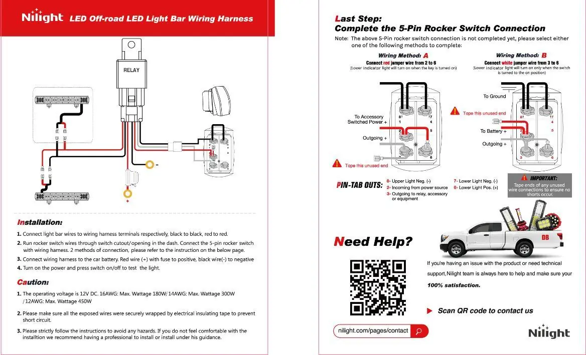
- Connect the light bar wires to the wiring harness terminals (black to black, red to red).
- Run the rocker switch wires through the switch cutout or opening in the vehicle dashboard.
- Connect the 5-pin rocker switch to the wiring harness using one of the two available connection methods.
- Connect the wiring harness to the car battery: connect the red wire (+) to the positive terminal and the black wire (-) to the negative terminal.
- Turn on the power and press the switch on/off to test the light.
5-Pin Rocker Switch Connection
The 5-pin rocker switch can be wired in two different ways to control the indicator light behavior:
- Wiring Method A: Connect the red jumper wire from pin 2 to pin 6. The lower indicator light will turn on when the key is turned on.
- Wiring Method B: Connect the white jumper wire from pin 3 to pin 6. The lower indicator light will turn on only when the switch is turned to the ON position.
Important: Tape the ends of any unused wire connections to ensure no shorts occur.
Pin-Tab Configuration
- Pin 8: Upper Light Neg (-)
- Pin 2: Incoming from power source
- Pin 3: Outgoing to relay, accessory, or equipment
- Pin 7: Lower Light Neg (-)
- Pin 6: Lower Light Pos (+)
Technical Specifications and Safety
Operating Voltage: 12V DC
Power Capacity by Wire Gauge:
- 16AWG: Max Wattage 180W
- 14AWG: Max Wattage 300W
- 12AWG: Max Wattage 450W
Safety Precautions:
- Ensure all exposed wires are securely wrapped with electrical insulating tape to prevent short circuits.
- If you do not feel comfortable with the installation, it is recommended to have a professional install the harness under their guidance.
Manufacturer information
Nilight
Practical help
Common problems
Lower indicator light behavior is incorrect
Use Method A (red jumper 2-6) for indicator on with key, or Method B (white jumper 3-6) for indicator on with switch.
Risk of short circuit
Ensure all exposed wire ends are securely wrapped with electrical insulating tape.
Before use
- Verify your vehicle system is 12V DC.
- Check the gauge of your light bar wires (16AWG, 14AWG, or 12AWG) to ensure it matches the harness capacity.
- Ensure you have a switch cutout/opening in the dash.
- Confirm you have electrical insulating tape for exposed connections.
Images and diagrams
- The main diagram illustrates the relay connection to the battery (Red +, Black -) and the light bar.
- The switch diagram details the jumper wire placement for the two different indicator light behaviors.
Model compatibility
- Designed for 12V DC systems only.
- Compatible with light bars requiring up to 450W depending on wire gauge.

Manual page author
Michael Turner
Technical manual editor
Reviews PDF manuals for structure, safety notes, and practical product details so readers can find the right information quickly.