Automotive / Electrical Accessories
Nilight 10014W LED Light Bar Wiring Harness Kit User Manual
Quick guide for the Nilight 10014W LED Light Bar Wiring Harness Kit. Includes installation steps, wiring methods for the 5-pin rocker switch, and power specifications.
Table of contents
Quick guide from the manual
This document provides installation instructions for the Nilight LED Off-road LED Light Bar Wiring Harness. It covers the physical connection of the harness to the light bar and battery, as well as specific wiring configurations for the 5-pin rocker switch.
Installation
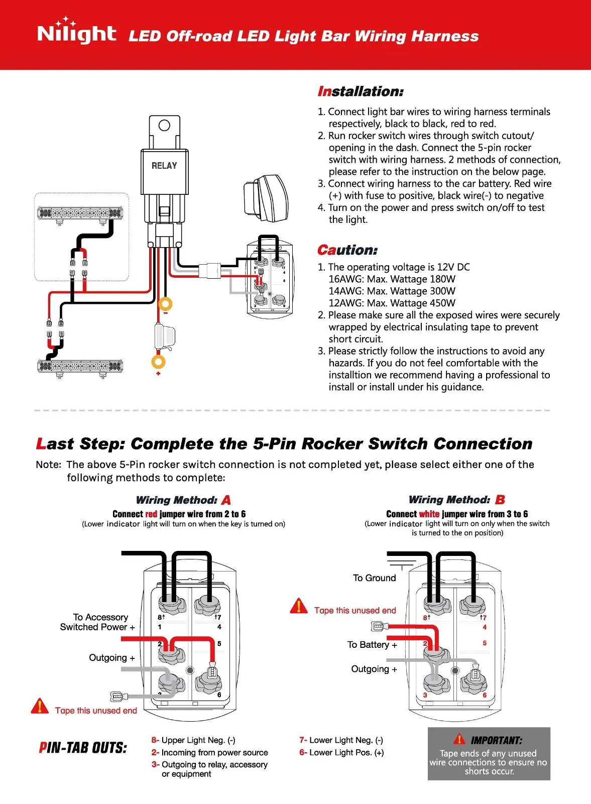
- Connect the light bar wires to the wiring harness terminals (black to black, red to red).
- Run the rocker switch wires through the switch cutout or opening in the dashboard.
- Connect the wiring harness to the car battery. Connect the red wire (with fuse) to the positive terminal and the black wire to the negative terminal.
- Turn on the power and press the switch to test the light.
Caution and specifications
Operating Voltage: 12V DC
Maximum Wattage by Wire Gauge:
- 16AWG: Max 180W
- 14AWG: Max 300W
- 12AWG: Max 450W
Safety Warning: Ensure all exposed wires are securely wrapped with electrical insulating tape to prevent short circuits. If you are not comfortable with the installation, it is recommended to have a professional perform or guide the installation.
5-Pin rocker switch connection
The 5-pin rocker switch can be wired in two different ways depending on your preference for the indicator light:
- Wiring Method A: Connect the red jumper wire from pin 2 to pin 6. The lower indicator light will turn on when the key is turned on.
- Wiring Method B: Connect the white jumper wire from pin 3 to pin 6. The lower indicator light will turn on only when the switch is turned to the ON position.
Important: Always tape the ends of any unused wire connections to ensure no shorts occur.
Pin-tab outs
- 8: Upper Light Neg. (-)
- 2: Incoming from power source
- 3: Outgoing to relay, accessory, or equipment
- 7: Lower Light Neg. (-)
- 6: Lower Light Pos. (+)
Manufacturer information
Nilight
Practical help
Common problems
Short circuit risk
Ensure all exposed wires are securely wrapped with electrical insulating tape.
Indicator light behavior
Use Wiring Method A if you want the indicator on with the key, or Method B if you want it on only when the switch is active.
Before use
- Verify the operating voltage is 12V DC.
- Check that your light bar wattage is compatible with your wire gauge (16AWG/14AWG/12AWG).
- Ensure you have electrical insulating tape for unused connections.
- Identify the correct wiring method (A or B) for your switch preference.
Images and diagrams
- The wiring diagram illustrates the connection path from the battery, through the relay, to the light bar and switch.
- The pin-tab diagram identifies the specific pin numbers (1-8) on the back of the rocker switch for correct jumper wire placement.
Model compatibility
- Designed for 12V DC systems only.

Manual page author
Emily Carter
User documentation editor
Prepares concise manual descriptions and highlights the most useful setup, operation, and maintenance information for readers.