Industrial / Cooling Units
Installation and Operating Instructions for nVent HOFFMAN SYSPEND 180-MAX Suspension System
A comprehensive installation and operating guide for the nVent HOFFMAN SYSPEND 180-MAX suspension system. This manual covers safety instructions, mechanical data, load capacity, mounting procedures for various components, adjustments, and...
Quick answers from the manual
Quick answer
- The SYSPEND 180-MAX is a modular suspension system for control enclosures. Installation involves mounting the base to a structure, attaching the tube system, and securing the enclosure using specific couplings. Always follow the torque specifications provided in the manual. p. 1, 4, 7
Key actions
- Mounting to plant or machine p. 4
- Adjusting firmness p. 11
- Earthing the system p. 19
Problems and fixes
Load capacity issues
Ensure mounting surface is smooth and flat; check load diagram.
p. 4Maintenance and reset
- Inspect tightening torques of screw connections on a regular basis. p. 3
Technical specifications
| Parameter | Value | Meaning | Pages |
|---|---|---|---|
| Protection class | IP 65 | Dust-tight and protected against water jets. | p. 4 |
Where to find it in the PDF
- Component pictograms p. 1
- Load diagram p. 4
- Earthing example p. 19
Table of contents
Manual images
Click an image to enlargeQuick guide from the manual
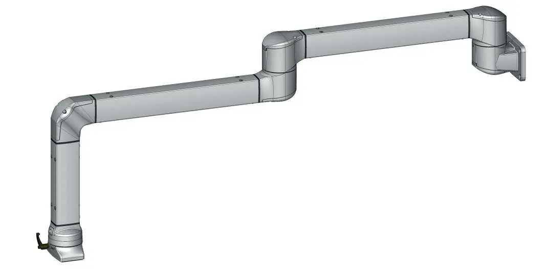
The SYSPEND 180-MAX is a modular suspension system. Installation begins with mounting the base to the plant, machine, or wall, followed by attaching the tube system and the enclosure. Always verify the load capacity using the provided diagram and ensure all screw connections are tightened to the specified torque.
Safety instructions
- Do not reach into the tubes.
- Avoid excessive crushing, stretching, or bending of power lines.
- Check the power line system regularly for abrasion points.
- Electrical connections must be performed by a qualified electrician.
- Do not damage seals during installation.
- Ensure the mounting surface is stable when using panel coupling components.
- Off-center installation on the control enclosure is not permitted.
- Inspect tightening torques of screw connections regularly.
Mechanical Data
The system components are made of GD-Al (Aluminum die-cast), with seals made of CR (Neoprene) / NBR and plastic parts made of POM. The system has an IP 65 protection class.
Installation and adjustment
Mounting to plant or machine
Ensure the mounting surface is smooth and flat to avoid load, adjustment, and protection class issues. Use the provided hole patterns (e.g., 100x60, 95x40, 60x60) and secure with appropriate fasteners.
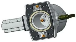
Tube mounting
For both vertical and horizontal mounting:
- Press the seal smoothly into place.
- Fit the screws into the support tube until flush with the inner surface.
- Push the tube onto the component.
- Tighten screws to 10-12 Nm.
- Check alignment with a spirit level.
Mounting to enclosure
Various couplings are available (Flange, Turn/tilt, Narrow adapter, VESA adapter, Panel coupling). Generally, lift the enclosure under the coupling, attach lock washers to screws, and tighten to 6 Nm. Ensure the mounting surface stability is sufficient.
Modification of firmness
The clamping lever or adjustment screw can be used to increase or decrease resistance. These are factory-preset to an optimum torque setting.
Accessories
Rotation limiters are available to restrict movement. The dust cap must be removed to insert the limiter, then replaced. Signal lamps can also be mounted to the system.
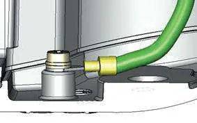
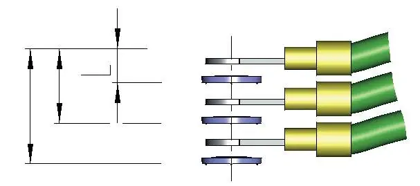
Earthing
The protective conductor system must comply with UL Standard UL 508A paragraph 14. Ensure the chosen cable length permits movement of the suspension system. Use serrated contact washers to separate each cable crimp.
Manufacturer information
nVent HOFFMAN
Practical help
Common problems
Load capacity issues
Ensure the mounting surface is smooth and flat. Check the load diagram on page 4 to ensure the extension arm length is within limits.
Instability or loose components
Regularly inspect the tightening torques of all screw connections. Ensure the mounting surface is stable.
Seal damage during installation
Handle seals carefully during installation; damaged seals may compromise the IP 65 protection class.
Before use
- Verify the mounting surface is smooth, flat, and stable.
- Ensure a qualified electrician is available for electrical connections.
- Check that the power line system is free from abrasion points.
- Verify that the chosen cable length allows for the full range of movement.
- Ensure all necessary tools (e.g., torque wrench) are available.
Specs in practice
- Tightening torque
- Specific force (Nm) required for screws to ensure stability (e.g., 6 Nm for enclosure mounting, 10-12 Nm for tube mounting).
- Static load capacity
- The maximum weight the suspension system can support, which decreases as the extension arm length increases.
Images and diagrams
- Pictograms on page 1 help identify specific components.
- The load diagram on page 4 illustrates the relationship between system load and extension arm length.
- Earthing diagrams on page 19 demonstrate the correct assembly of the protective conductor system.
Model compatibility
- Designed for central mounting on control enclosures; off-center installation is not permitted.
- Narrow adapters must only be used in conjunction with Flange Couplings and Flange Elbow Couplings.
- The system is designed for specific nVent HOFFMAN components.

Manual page author
Michael Turner
Technical manual editor
Reviews PDF manuals for structure, safety notes, and practical product details so readers can find the right information quickly.