Electronics / PA Systems
User Manual for Potter ATTE-B Fire Alarm & Trouble Transmitter
Quick guide for the Potter ATTE-B Fire Alarm & Trouble Transmitter. Includes installation, wiring diagrams, code wheel configuration, and operational testing procedures.
Table of contents
Manual images
Click an image to enlargeImportant Information
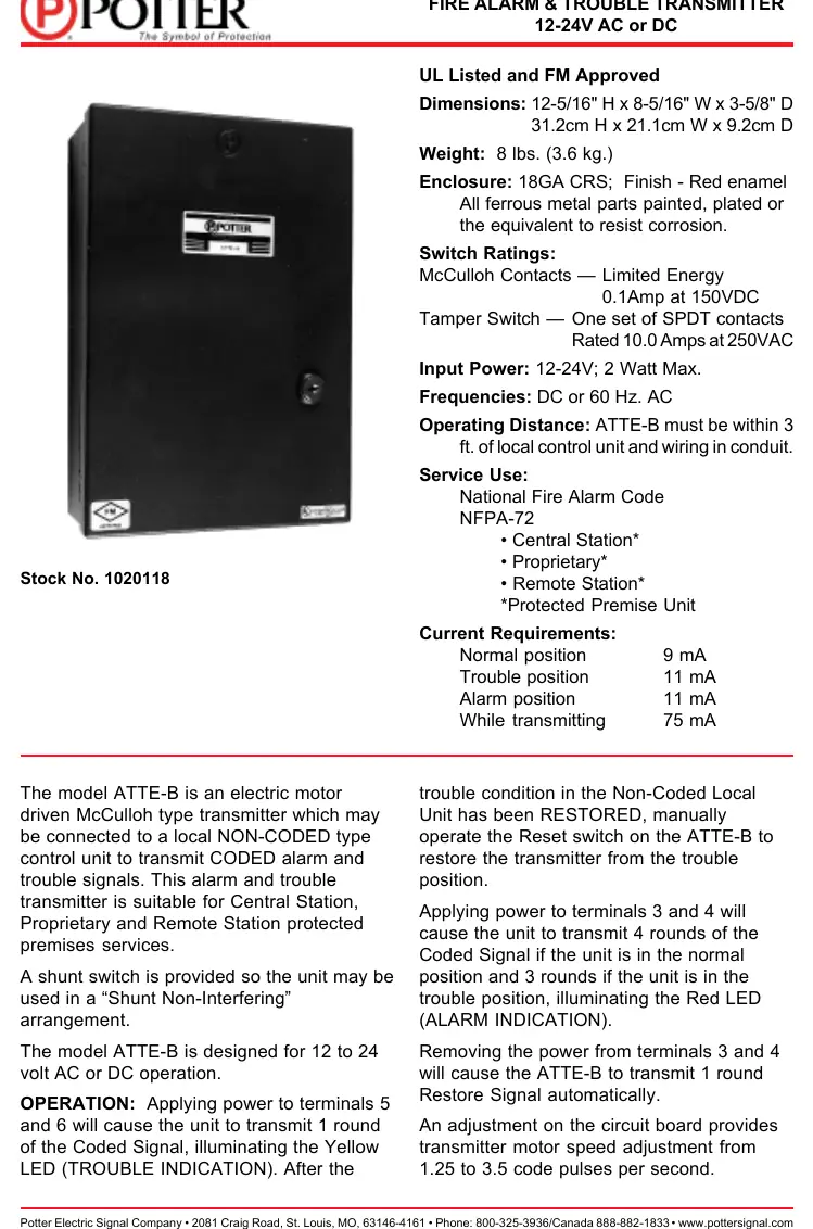
The Potter ATTE-B is an electric motor-driven McCulloh type transmitter designed for 12-24V AC or DC operation. It is intended to be connected to a local non-coded control unit to transmit coded alarm and trouble signals. Important constraints: The unit must be located within 3 feet of the non-coded control unit, and all interconnect wiring must be in conduit. The transmitter should be tested on a monthly basis to ensure proper operation.
Product Overview
The ATTE-B is suitable for Central Station, Proprietary, and Remote Station protected premises services. It features a shunt switch for "Shunt Non-Interfering" arrangements and includes both Yellow (Trouble) and Red (Alarm) LED indicators.
Installation
Installation must be performed by qualified personnel. Follow these steps:
- Mount the ATTE-B enclosure securely.
- Ensure all wiring between the non-coded control and the ATTE-B is in conduit.
- The unit must be within 3 feet of the control unit.
- Ensure the code wheel is configured before applying power (see Code Wheel Configuration).
- Connect alarm and trouble inputs, central office line, earth ground, and shunt according to the wiring diagram.
Code Wheel Configuration
The code wheel must be prepared before the unit is powered:
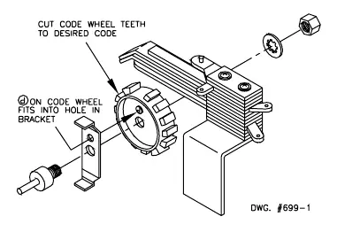
- Remove the code wheel and the metal bracket.
- Cut the code wheel teeth to the desired code.
- Reinstall the code wheel and bracket. Ensure the bracket tab is centered in the slot of the black opto device (U8) on the circuit board.
- Hold the assembly in position and tighten the mounting nut.
Wiring Instructions
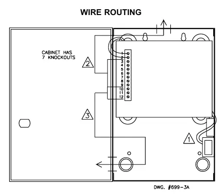
The enclosure provides multiple cable entry openings to segregate "Power Limited" fire protective signaling conductors from Class 1 "Non-power Limited" conductors.
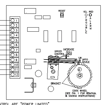
- Power Inputs: Terminals 3 and 4 (Alarm), Terminals 5 and 6 (Trouble).
- Routing: Use the top center knockout for wires from terminals 3 through 9. Use the lower left-hand side for wires from terminals 10 through 12.
- Tamper: Run cover tamper wire under the P.C. board to terminals 1 and 2.
Operation
The transmitter responds to voltage inputs from the non-coded control unit:
- Alarm Signal: Applying power to terminals 3 and 4 triggers 4 rounds of the coded signal (Red LED illuminates).
- Trouble Signal: Applying power to terminals 5 and 6 triggers 1 round of the coded signal (Yellow LED illuminates).
- Restore: Removing power from terminals 3 and 4 causes the unit to transmit 1 round of the restore signal.
- Reset: After a trouble condition is restored, manually operate the Reset switch on the ATTE-B to restore the transmitter to the normal position.
Maintenance
The transmitter should be tested monthly. Verify that the central office receives clear and intelligible signals during testing. Ensure the cover is closed and the tamper switch is engaged for normal operation.
Practical help
Common problems
Transmitter fails to signal
Check power connections to terminals 3/4 or 5/6 and ensure the non-coded control unit is functioning.
Code wheel not operating correctly
Ensure the bracket tab is properly centered in the slot of the black opto device (U8) on the circuit board.
Tamper alarm active
Ensure the cover is fully closed and the tamper switch plunger is depressed.
Before use
- Verify power source is 12-24V AC or DC.
- Ensure unit is mounted within 3 feet of the non-coded control unit.
- Confirm all interconnect wiring is installed in conduit.
- Cut the code wheel to the desired code before applying power.
- Ensure the bracket tab is centered in the opto device slot.
Specs in practice
- Operating Distance
- Must be within 3 feet of the local control unit.
- McCulloh Contacts
- Limited Energy, 0.1Amp at 150VDC.
- Tamper Switch
- SPDT contacts rated 10.0 Amps at 250VAC.
Images and diagrams
- Fig 1: Illustrates the removal, cutting, and reinstallation of the code wheel and bracket.
- Fig 2: Provides the terminal wiring diagram and component layout.
- Fig 3: Shows the enclosure cable entry points for segregating power-limited and non-power-limited conductors.
- Fig 4: Details the specific wire routing paths through the cabinet knockouts.
Model compatibility
- Compatible with non-coded type control units.
- Suitable for Central Station, Proprietary, and Remote Station protected premises services.
- All input circuits must be power limited.

Manual page author
Emily Carter
User documentation editor
Prepares concise manual descriptions and highlights the most useful setup, operation, and maintenance information for readers.