Electronics / PA Systems
Installation and Operation Manual for Potter PVX 100M Mass Notification System
Quick guide for the Potter PVX 100M Mass Notification System. Includes installation, wiring diagrams, switch settings, and operational guidelines for FACP and standalone configurations.
Table of contents
Manual images
Click an image to enlargeQuick Guide from the Manual
The PVX 100M is a Voice Evacuation/Mass Notification System (MNS) module. It is designed to operate in conjunction with a UL listed Fire Alarm Control Panel (FACP) or as a standalone system. Key requirements include a 120 VAC, 60 Hz power supply and ensuring all connected equipment is located in the same room, within 20 feet, and piped together.
System Overview
The PVX 100M provides 100W of audio power. It supports speaker circuits at 25V or 70 Vrms (factory set to 25V via jumper). The system includes internal supervision for speaker lines and accessories, reporting faults back to the FACP.
Switch Settings
The system features two banks of switches (SN1 and SN2) for configuring fire tones and messages. Note: All switch settings refer to Fire Tone/Message only. MNS Tone/Messages must be pre-configured for the system.
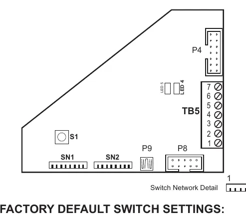
- SN1: Configures settings such as Temporal Whoop Signal, Fault Code Lock, AC Fault Delay, Battery connection, and Mic connection.
- SN2: Configures delays (initial and repeat), Message On status, and number of repeats.
Wiring and Connections
The system requires specific wiring configurations depending on the setup:
- Power: 120 VAC at 60 Hz.
- Wiring Guide: Use 22 AWG min. twisted pair. Max wire resistance is 120 Ohms, max capacitance is .5uf, and max wire length is 4000 feet.
- Connections: Terminals are provided for Circuit Neg, +24VDC, Audio (+/-), and RS 485 (+/-).
- Modules: The system can be combined with PVC-100E expanders, PVC-ZM for zoning, PVC-SL8/OL8/IL8 for inputs/outputs, and PVC-RM8.
Operational Guidelines
The PVX 100M supports two primary operational modes:
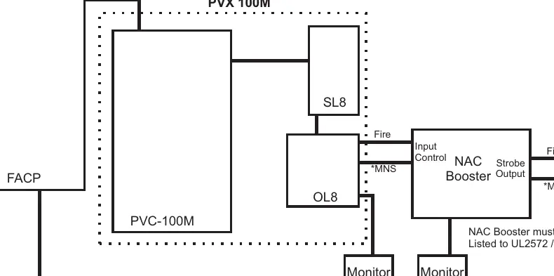
- With FACP: The FACP monitors the PVX 100M for fault and supervisory conditions. If an MNS signal overrides the FACP alarm, a PVC-OL8 output point is required to report the condition as a supervisory event.
- Standalone: In the absence of an FACP, the PVX 100M must use a PVC-SL8 with its first position Switch/LED programmed for Power/Fault reporting. The LED indicates status: Steady Green for Normal, Flashing Amber for Fault (except AC loss), and Steady On for AC loss.
Zoning
When required, a PVC-ZM module can be used for separate speaker circuits. These can be activated via 'All Call' or manual selection using the PVC-SL8. Default operation is 'All Call' on any Alarm/MNS event.
Practical help
Common problems
Fault reported by FACP
Check speaker lines, accessories, and internal supervision. Ensure EOLR is connected to the supervisory circuit.
MNS signal override issues
Ensure a PVC-OL8 is installed with an output point programmed for MNS to allow the FACP to report the condition as a supervisory event.
Amber Strobe monitoring
If Amber Strobes are used, they must be monitored separately. Use a PVC-IL8 input programmed for Fault.
Before use
- Verify power supply is 120 VAC, 60 Hz.
- Ensure all external control devices are Listed to UL2572/UL2017.
- Confirm all equipment is in the same room, within 20 feet, and piped together.
- Check jumper settings for speaker voltage (25V factory set).
- Ensure all wiring meets the 22 AWG min. twisted pair specification.
Specs in practice
- Speaker Voltage
- Selectable between 25V or 70 Vrms via jumper.
- Max Wire Length
- 4000 feet maximum for 22 AWG twisted pair.
Images and diagrams
- Switch Network Detail: Shows the configuration banks SN1 and SN2 for fire tones and message settings.
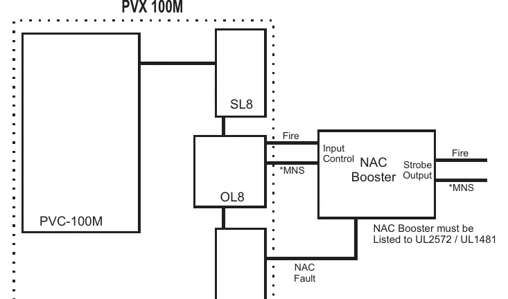
- Wiring Diagrams: Illustrate the connection paths between the PVX 100M, FACP, NAC Booster, and various modules like SL8, OL8, and IL8.
Model compatibility
- Compatible with UL listed Fire Alarm Control Panels (FACP).
- Supports expansion with PVC-100E, PVC-ZM, PVC-SL8, PVC-OL8, PVC-IL8, and PVC-RM8 modules.
- NAC Booster must be Listed to UL2572 / UL1481.

Manual page author
Emily Carter
User documentation editor
Prepares concise manual descriptions and highlights the most useful setup, operation, and maintenance information for readers.