Electronics / RFID Barcode Scanners
Installation and Commissioning Guide for Honeywell Fire Control and Repeat Panels
Comprehensive installation and commissioning guide for Honeywell conventional fire control and repeat panels (1, 2, 4, and 8 zone). Includes wiring diagrams, setup instructions, programming options, and fault troubleshooting.
Table of contents
Manual images
Click an image to enlargeQuick guide from the manual
This document provides essential installation, commissioning, and configuration information for Honeywell conventional fire control and repeat panels. It is intended for use by installers and commissioning engineers. Ensure all local regulations and standards, such as BS 5839:Part 1:2013, are followed during installation.
System design and wiring
The fire system design must comply with relevant standards. Key wiring requirements include:
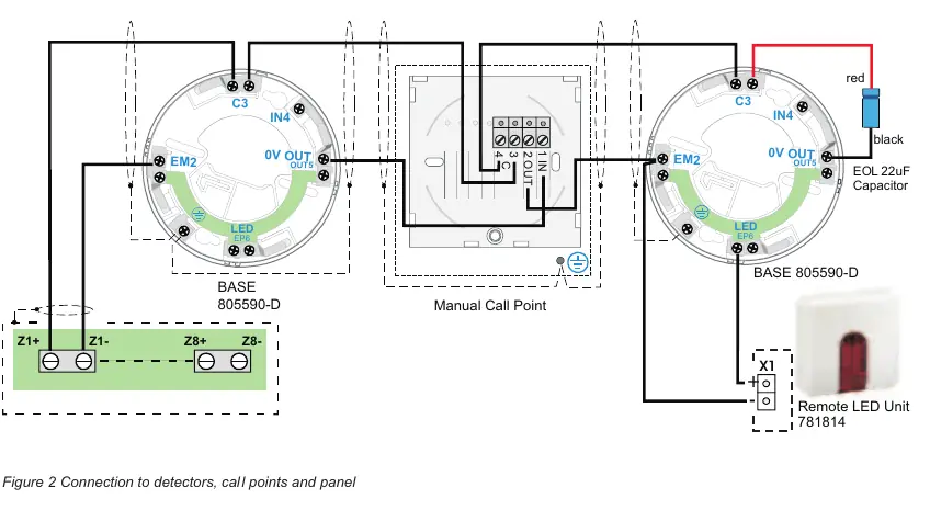
- Zone circuits: Each zone can support up to 3.0mA load. End-of-line capacitor units or bipolar capacitors are required for monitoring. Manual call points must have a 470 ohms series resistor.
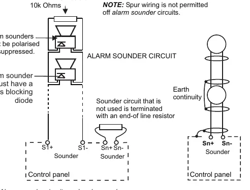
- Sounder circuits: Alarm sounders must be polarized and suppressed. The last sounder must be fitted with a 10K Ohm end-of-line resistor.
- Cabling: Use generally available electrical installation cable (BS6387 compliant) with no more than 2 cores, minimum 1.5mm² cross-section.
- Power supply: The control panel must be connected via a fused spur unit (5A for 2-zone/repeat panels, 7A for 4 & 8-zone panels).
Panel installation
Follow these steps to install the panel:
- Remove the panel from the carton and store the front panel/electronic assembly safely.
- Remove the appropriate knock-in for cable entry.
- Mark and drill fixing holes on the wall.
- Secure the panel to the wall using suitable fixings.
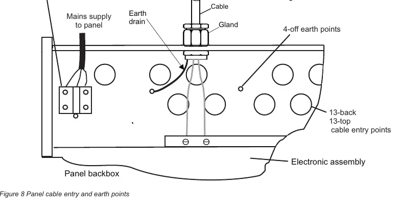
- Connect the mains supply cable to the dedicated entry points.
- Wire the system, leaving 300mm tail wire length for connections.
- Refit the front panel using M3 screws and connect the transformer and earth cables.
Power-up and testing
Before powering up, ensure all cables are marked and disconnected from terminals. Connect end-of-line units to zone and sounder circuits. Switch on mains power, then connect the battery supply. Verify the green power light is lit. Perform open and short circuit tests on all zones and sounder circuits to ensure correct operation.
Controls and indicators
The panel features a numeric keypad and various indicators:
- Essential controls: Include Cancel Buzzer, System Reset, Sound Alarms, and Silence Alarms.
- Indicators: Provide status for Fire, Fault, System, Power, Earth, Sounder, Disabled, Test, and Delay.
- Access levels: Different access levels (AL1-AL4) are protected by codes (default AL2: 123, AL3: 321, AL4: 7426).
Programming options
The panel settings can be customized using the numeric keypad after entering the appropriate access code. Functions include configuring zone latching, reset silence configuration, and false alarm rejection. Note that the EEPROM protection link must be removed to access programming mode and refitted afterward.
Fault indications
In the event of a fault, the common Fault light will illuminate, and the internal buzzer will sound. Common faults include:
- Zone fault: Open/short circuit or missing end-of-line capacitor.
- Sounder fault: Open/short circuit or missing end-of-line resistor.
- Mains/Battery fault: Power supply issues or battery failure.
- Earth fault: Electrical path to earth detected.
Manufacturer information
Honeywell International Inc.
Practical help
Common problems
Zone fault
Check for open or short circuit on the zone cable, or ensure the end-of-line capacitor unit is correctly fitted.
Sounder fault
Check for open or short circuit on the sounder cable, or ensure the end-of-line resistor is correctly fitted.
Battery fault
Check battery connections, battery health, or the battery fuse.
Earth fault
Inspect system wiring for any electrical path to earth connections.
Before use
- Ensure 'as fitted' drawings are available.
- Verify system is installed according to project requirements.
- Check mains supply is via a fused spur unit.
- Ensure batteries are connected correctly.
- Verify EEPROM protection link is fitted.
Specs in practice
- Zone circuit load
- Maximum 3.0mA per zone.
- Sounder output
- 0.5A max per output, protected by 0.75A resettable fuse.
- Auxiliary contacts
- Rated 1A @ 24V dc resistive load.
Images and diagrams
- Figure 1: Zone circuit wiring for used and unused circuits.
- Figure 2: Connection diagram for detectors, call points, and the panel.
- Figure 3: Alarm sounder circuit wiring.
- Figure 8: Panel cable entry and earth points.
- Figure 12: Panel terminals and fuse locations.
Model compatibility
- Compatible with BS 5839:Part 1:2013.
- Requires end-of-line capacitor/resistor units.
- Manual call points must have a 470 ohms series resistor.

Manual page author
Emily Carter
User documentation editor
Prepares concise manual descriptions and highlights the most useful setup, operation, and maintenance information for readers.