Power / Electrical Connectors
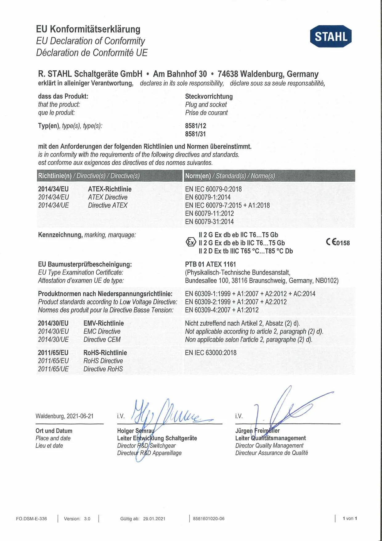
User Manual for R. Stahl SolConeX 125A Explosion-Proof Outlet Series 8581/31
Quick guide for the R. Stahl SolConeX 125A explosion-proof outlet (Series 8581/31). Includes installation, wiring, safety, and maintenance instructions.
Table of contents
Manual images
Click an image to enlargeQuick Guide
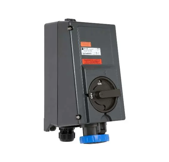
The R. Stahl SolConeX 8581/31 is an explosion-proof outlet designed for use in hazardous areas (Zones 1, 2, 21, and 22). This guide covers essential installation, operation, and maintenance procedures. Always ensure the device is installed by qualified personnel and that all safety regulations are followed.
Safety and Usage
The device is designed for connecting portable and fixed electrical equipment in hazardous areas. Safety Precautions:
- Ensure the device is in perfect condition before installation.
- Only use in accordance with the specified hazardous zone ratings.
- Do not modify or convert the device.
- Always disconnect power before assembly, disassembly, or maintenance.
- Use only original R. Stahl spare parts.
Installation
The device is suitable for indoor and outdoor use. It is recommended to install a protective roof or wall in outdoor environments.
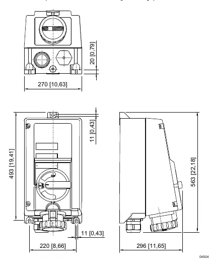
Mounting
The outlet should be fixed to a flat surface using 3 bolts and appropriate washers. The mounting holes are slotted to allow for adjustment.
Auxiliary Contacts
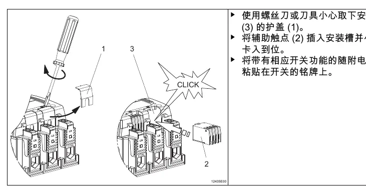
The standard version includes one auxiliary contact (8080/1-1). Up to two auxiliary contacts can be installed. To install, remove the cover of the installation slot, insert the contact until it clicks, and attach the circuit diagram to the nameplate.
Wiring
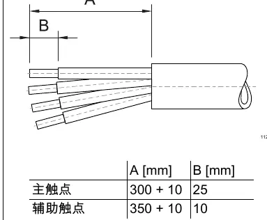
Ensure that intrinsically safe and non-intrinsically safe circuits are separated according to the required distances. Use appropriate cable glands and ensure conductors are stripped and inserted correctly into the terminals. Tighten all cable glands and terminals to the specified torque.
Operation
The outlet is designed for use with R. Stahl 8581/12 plugs. The switch can be locked in the 0 or I position using a padlock (max. diameter 8 mm). Ensure the plug is fully inserted and the locking ring is tightened to maintain the IP protection rating.
Maintenance and Cleaning
Regular maintenance is required to ensure safe operation:
- Inspect the housing and seals for cracks or damage.
- Check that all fixings and cables are secure.
- Ensure the device is free of dust and contaminants.
- Clean only with a damp cloth; do not use high-pressure water or abrasive cleaners.
- If a short circuit occurs in the main circuit, the entire outlet flange must be replaced.
Technical Data
Key specifications for the 8581/31 series:
- Rated Current: 125 A
- Rated Voltage: Up to 690 V AC / 220 V DC
- Protection Class: IP66
- Impact Strength: IK 10
- Cable Gland: M63 x 1.5
- Operating Temperature: -45 °C to +60 °C
Manufacturer information
R. STAHL AG
Practical help
Common problems
Explosion hazard due to improper installation
Ensure the device is installed by qualified personnel, use original parts, and verify the hazardous zone rating.
Overheating or static accumulation
Operate only within specified technical data limits; ensure proper cable cross-section and use only damp cloths for cleaning.
Auxiliary contact malfunction
Ensure the contact is correctly snapped into the slot and that Ex i covers are used if required.
Before use
- Check for mechanical damage to the housing or seals.
- Verify the device is suitable for the intended hazardous zone.
- Ensure all cable glands and plugs are tightened.
- Verify the supply voltage matches the device rating.
- Ensure the device is clean and free of foreign objects.
Specs in practice
- Rated Current
- 125 A
- Protection Class
- IP66 (Dust-tight and protected against powerful water jets)
Images and diagrams
- Mounting diagram shows the 3-bolt fixation pattern on a flat surface.
- Wiring diagram indicates stripping lengths for main and auxiliary contacts.
- Auxiliary contact installation shows the snap-in mechanism and cover removal.
Model compatibility
- Only use R. Stahl 8581/12 plugs.
- Suitable for Zones 1, 2, 21, and 22.

Manual page author
Emily Carter
User documentation editor
Prepares concise manual descriptions and highlights the most useful setup, operation, and maintenance information for readers.