Power / Electrical Connectors
User Manual for R. Stahl SolConeX Connector 8581/12
Quick guide for the R. Stahl SolConeX 8581/12 125A connector. Includes installation, wiring, safety instructions, technical specifications, and maintenance procedures for hazardous areas.
Table of contents
Manual images
Click an image to enlargeImportant Information
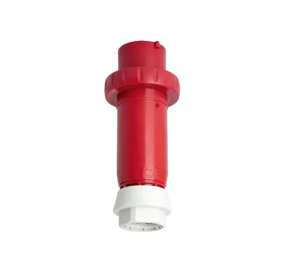
The R. Stahl SolConeX 8581/12 is an explosion-protected industrial connector designed for use in hazardous areas (Zone 1, 2, 21, and 22). This manual provides essential instructions for installation, operation, and maintenance. Always ensure that the device is used within its specified operating conditions and that all work is performed by qualified personnel.
Safety Instructions
The device is designed for use in explosive atmospheres. Failure to follow safety instructions can result in serious injury or death. Key safety requirements include:
- Do not open the device while under voltage.
- Ensure the device is not damaged before installation.
- Use only in environments where the device is certified for use.
- Ensure the bayonet ring is fully locked to maintain IP protection.
- Clean the device only with a damp cloth to prevent electrostatic discharge.
Installation and Wiring
Installation must be carried out by qualified personnel according to local regulations. Follow these steps for wiring:
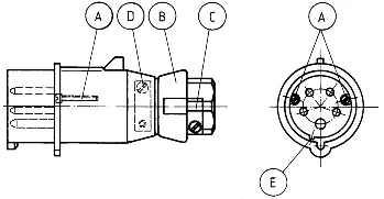
- Loosen screw (A) and remove the connector insert from the housing.
- Loosen clamp (C) and pressure screw (B).
- Remove the dust plate, pressure ring, and seal from the housing.
- Feed the cable through the pressure screw, pressure ring, seal, and housing.
- Strip the cable insulation and connect the wires to the connector insert, ensuring they are fully inserted into the terminals.
- Secure the cable strain relief (D).
- Reassemble the connector, ensuring the nose and guide slot (E) are aligned.
- Tighten the pressure screw (B) and secure with clamp (C).
Torque Settings:
- Terminals: 3.5 Nm
- Housing screws: 2.5 Nm
- Strain relief: 3.5 Nm
Operation
The connector is compatible with R. Stahl wall sockets 8581/11 and 8581/31 and complies with DIN EN 60309 standards. Before inserting the plug, ensure the contacts are clean and dry. Always lock the bayonet ring completely after insertion to maintain the IP66 protection rating.
Maintenance and Cleaning
Regular maintenance is required to ensure safe operation:
- Inspect the device for cracks, damage, and contamination.
- Check that all electrical connections are tight.
- Clean the device using a damp cloth; do not use abrasive or corrosive cleaners.
- After 1000 connection cycles, clean the connector and apply a recommended lubricant (e.g., Klübersynth PTB 2-24). Do not use mineral-based lubricants.
Technical Data
- Rated Voltage: Max 690V AC / 220V DC
- Rated Current: 125A
- Frequency: 50/60Hz (Derate to 100A if frequency > 100Hz)
- Operating Temperature: -45°C to +60°C
- Protection Class: IP66 (Dust-tight and water-jet resistant)
- Impact Resistance: IK10
- Connection Cross-section: 2.5 to 35mm² (AWG 14 to AWG 2); 50mm² (AWG 1) for pin terminals
Manufacturer information
R. STAHL AG
Practical help
Common problems
Connector overheating
If the frequency is above 100Hz, the current must be derated to 100A.
Explosion risk during operation
Ensure the bayonet ring is fully locked and the device is free of dust and moisture before use.
Cable connection failure
Ensure the cable diameter is within the 30-45mm range and that the correct torque (3.5Nm) is applied to terminals.
Before use
- Verify the device is not damaged.
- Ensure the installation area is suitable for the device's explosion protection rating.
- Check that the cable diameter matches the cable gland range (30-45mm).
- Verify all electrical connections are tight and torque settings are applied.
- Ensure the bayonet ring is fully locked.
Specs in practice
- Zone 1, 2, 21, 22
- Suitable for hazardous areas with explosive gas and dust atmospheres.
- 690V AC / 220V DC
- Maximum rated operating voltage.
Images and diagrams
- Wiring diagram shows the connection points A, B, C, D, E for the connector assembly.
- Dimensions diagram provides the necessary clearance and size specifications for installation.
Model compatibility
- Compatible with R. Stahl wall sockets 8581/11 and 8581/31.
- Complies with DIN EN 60309 industrial standards.

Manual page author
Michael Turner
Technical manual editor
Reviews PDF manuals for structure, safety notes, and practical product details so readers can find the right information quickly.