Industrial / Weighing Equipment
Installation Manual for Rice Lake Weighing Systems MASTER 14x Belt Scale Weigh Frame
Comprehensive installation and maintenance guide for the Rice Lake Weighing Systems MASTER 14x Belt Scale Weigh Frame. Includes mechanical and electrical installation steps, safety precautions, and technical specifications.
Table of contents
Manual images
Click an image to enlargeQuick guide from the manual
The MASTER 14x Belt Scale Weigh Frame is designed for heavy-duty industrial applications. This manual covers the mechanical and electrical installation, commissioning, and maintenance of the system. Key requirements for successful installation include a stable, vibration-free conveyor environment, proper idler alignment, and adherence to welding safety protocols to protect the load cells.
Safety
DANGER: Failure to follow safety instructions can result in death or serious injury. Always turn off the power supply before making or removing connections. When welding, the welding ground clamp must be attached to the same side of the weigh frame where welding is occurring, or the load cells must be removed to prevent damage.
General Safety Precautions:
- Wear safety shoes and protective eye wear during installation.
- Keep hands, feet, and loose clothing away from moving parts.
- Do not approach or bend over a running conveyor.
- Do not operate without all shields and guards in place.
- Do not use any load-bearing component worn beyond 5% of its original dimension.
- Do not exceed the rated load limit.
Overview
The 14x Master Belt Scale Weigh Frame is designed for heavy-duty process industry applications. It uses one or more idlers mounted on a weigh frame to weigh material on a belt. The system calculates mass flow based on belt load and belt speed, transmitting this data to a control system or network. Operation requires specific integrator electronics; refer to the manual provided with your electronics for operational details.
Selection Criteria
Load cell capacity is determined by the maximum belt load plus the dead load of the weigh frame and rollers. The 14x uses four RL20000 S-beam load cells. The total load cell build capacity should be approximately equal to or greater than double the calculated Gross Load.
Mechanical Installation
The mechanical installation involves mounting the weigh frame, speed pickup, and junction box.
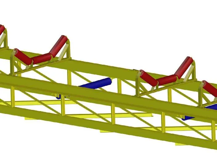
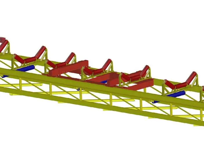
- Determine the location for the weighing idler (at least five idlers after the load point and five before the head pulley).
- Measure the center-to-center distance of the idlers for accurate placement.
- Remove the existing idler where the weigh frame will be located.
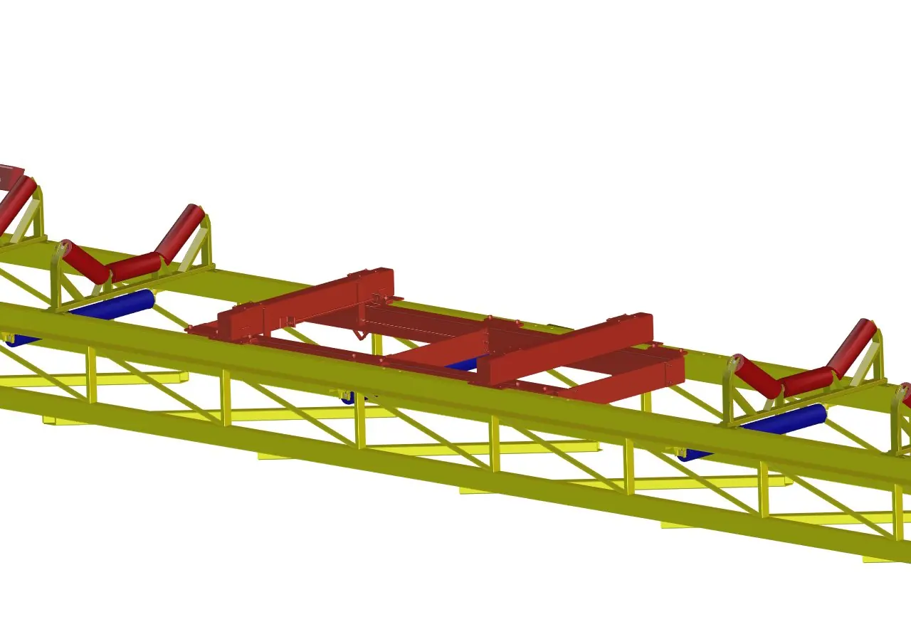
- Install the weigh frame to the conveyor.
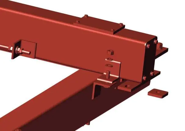
- Remove the shipping block from the load bridge assembly.
- Modify the idler station by removing mounting feet if necessary.
- Drill hole locations for bridge mounting bolts and secure the weldment with four 1/2 inch bolts.
- Run strings on the conveyor (three before and three past the scale) and shim the idlers to the same plane.
Electrical Installation
Wiring and connections between the weigh frame, speed pickup, and electronics must follow the applicable scheme. The load cell comes with a fixed cable; do not alter its length. If extension is required, use an additional junction box with screw terminals.
- Load Cell: For lengths over 197 feet (60 meters), use shielded 6-wire 20 AWG cable.
- Speed Pickup: Use shielded 3-wire 20 AWG cable.
- Shielding: Connect cable shielding to one side only. If connected to the instrument side, use the same ground as the power supply.
Commissioning
Commissioning should be performed by trained service engineers. Mechanical adjustments must be made to ensure the scale is free of any tension. If necessary, the load cell can be adjusted.
Maintenance
Regular maintenance is essential to prevent errors and downtime.
- Periodical Maintenance: Ensure there is no debris build-up on the belt.
- Inspection: Regularly inspect the weigh frame for damage and repair as necessary.
- Calibration: Perform an Auto Zero and weight check with certified test weights regularly. Refer to the electronics manual for the specific procedure.
Specifications
Weigh Frame Material: Powder-coated mild steel or Stainless Steel SS304 / 316.
Weight: Approximately 104 lb (47 kg) excluding the idler.
Load Cells: 4 S-Beam (stainless steel IP67), capacity 2.5K - 5 Klb.
Power Supply: 5-15 VDC (stabilized from electronics).
Signal: Nominal 3 mV/V at 100% load.
Practical help
Common problems
Load cell damage during welding
Always attach the welding ground clamp to the same side of the weigh frame where welding is occurring, or remove the load cells entirely before welding.
Inaccurate weighing due to belt issues
Ensure the belt is of good quality with a single splice. The belt must not track out of the center, and no steering idler should be placed near the weighing area.
Vibration interference
Ensure the conveyor is installed in a stable, rigid area. If vibrations from the conveyor carry over to the weigh frame, they must be filtered.
Before use
- Ensure the conveyor is in a stable, rigid area free from vibrations.
- Verify the belt is of good quality with a single splice.
- Check that the weigh frame is mounted free of mechanical tensions.
- Ensure side guards and belt skirting are not in contact with the weighing area.
- Confirm the inclination angle of the belt conveyor does not exceed 25 degrees.
- Ensure all shields and guards are in place.
Specs in practice
- Power Supply
- 5-15 VDC, stabilized from the electronics.
Images and diagrams
- Figure 2-1: Measuring center-to-center distance of idlers for proper placement.
- Figure 2-5: Modification of idler station by removing mounting feet.
- Figure 3-1: Dimensional layout of the 14x weigh frame.
Model compatibility
- Requires specific integrator electronics (refer to separate manual).
- Not suitable for every application; must be analyzed by a Rice Lake specialist.

Manual page author
David Miller
Documentation analyst
Organizes user manual content into clear summaries, with attention to model details, product context, and everyday usability.