Toys / RC Components
User Manual for RunCam Eagle 3 FPV Camera
Quick guide for the RunCam Eagle 3 FPV camera. Includes wiring diagrams, OSD menu navigation, installation dimensions, and technical specifications.
Table of contents
Manual images
Click an image to enlargeQuick guide from the manual
The RunCam Eagle 3 is a high-performance FPV camera designed for RC aircraft. This guide covers the essential wiring, menu navigation, and technical specifications required for setup and operation. Ensure your power supply is within the 5-36V DC range before connecting.
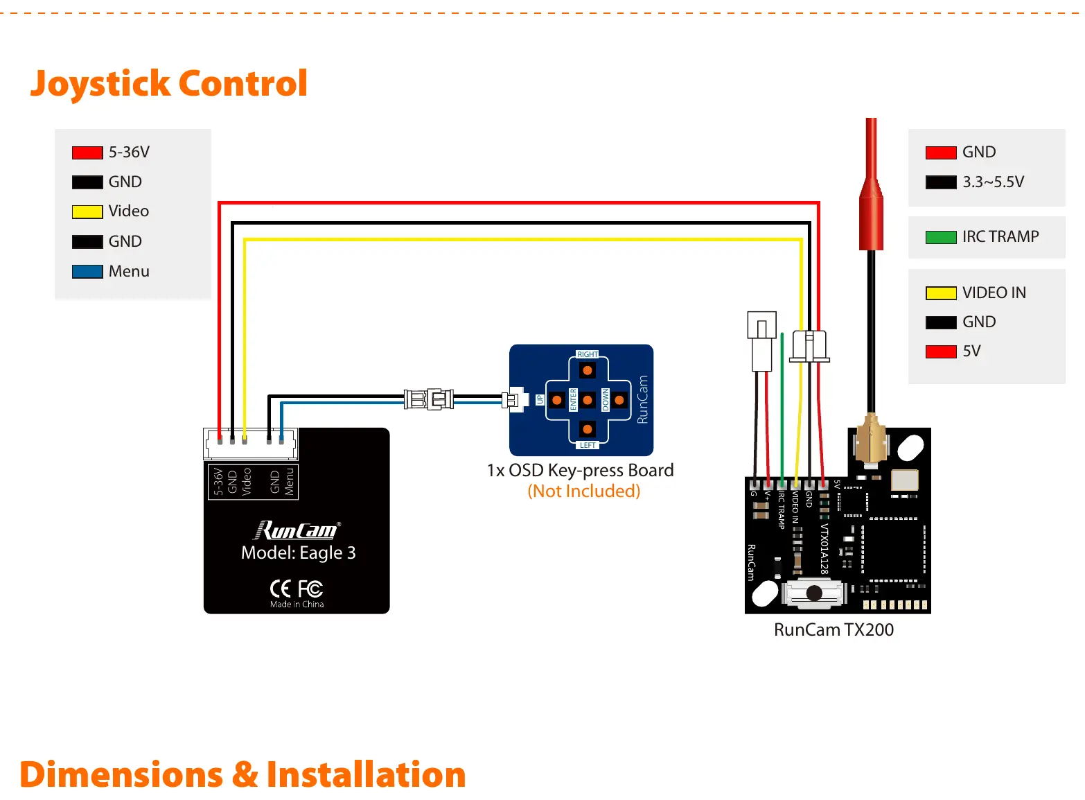
Wiring and Joystick Control
The camera features a 5-pin connector for power, video, and menu control. Use the provided OSD key-press board to navigate the camera settings. The wiring diagram illustrates connections for the 5-36V power input, Ground (GND), Video output, and Menu control pins. Ensure the OSD board is connected to the Menu and GND pins to access the settings menu.
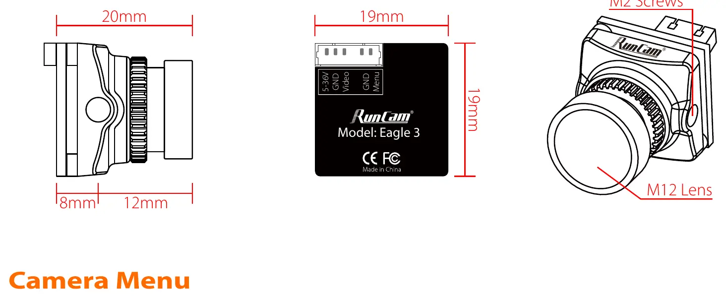
Dimensions and Installation
The camera housing measures 19mm x 19mm x 20mm. It utilizes an M12 lens mount. When installing, ensure the M2 screws are used for secure mounting. The compact design is suitable for standard FPV camera mounts.
Camera Menu
Access the OSD menu using the joystick on the OSD key-press board. The menu allows for the following adjustments:
- Exposure: Adjust brightness and exposure mode (Globe/BLC).
- WB (White Balance): Set to ATW or MWB.
- Day/Night: Configure mode (Color, BW, EXT, Auto).
- Video Setting: Adjust image ratio (4:3 or 16:9) and horizontal/vertical inversion.
- Image Enhance: Fine-tune contrast, sharpness, color gain, and 3DNR settings.
Technical Parameters
Key specifications for the RunCam Eagle 3 include:
- Image Sensor: 1/2.8" Starlight CMOS Sensor
- Resolution: 1000TVL
- Lens: 2.1mm (M12) FOV 155°
- Signal System: NTSC only
- Power Input: DC 5-36V
- Current Consumption: 220mA at 5V / 120mA at 12V
- Weight: 9g
- Housing Material: ABS
Practical help
Common problems
No video signal
Verify that the Video and GND wires are securely connected to your video transmitter or receiver. Ensure the power supply is within the 5-36V range.
Cannot access OSD menu
Ensure the OSD key-press board is correctly connected to the Menu and GND pins on the camera cable.
Before use
- Verify power source is between 5V and 36V DC.
- Ensure correct wiring of Video, GND, and Power pins.
- Check that the lens is securely mounted (M12).
- Confirm your video receiver is compatible with NTSC signal format.
Images and diagrams
- The wiring diagram shows the pinout for the 5-pin connector, including connections for the OSD key-press board and a video transmitter like the RunCam TX200.
Model compatibility
- Signal System: NTSC only.

Manual page author
Emily Carter
User documentation editor
Prepares concise manual descriptions and highlights the most useful setup, operation, and maintenance information for readers.