Industrial / Electrical
Instruction Manual for Schneider 140CRA93100 RIO Drop Adaptor Module
A comprehensive guide for the installation, cabling, and commissioning of the Schneider 140CRA93100 RIO Drop Adaptor Module, including network topology requirements, grounding, and attenuation limits.
Table of contents
Manual images
Click an image to enlargeQuick guide from the manual
This document provides essential guidelines for the installation and commissioning of the RIO network using the 140CRA93100 RIO Drop Adaptor. Key requirements include maintaining strict network topologies, adhering to specific cable lengths, and ensuring proper grounding and impedance termination to prevent communication errors.
Network Topologies
The RIO network is a single-master system with the RIO processor (140CRP93x00) as the master node. A Quantum RIO network supports up to 31 drops. Topologies are precisely defined (single, dual, or redundant cable systems) and must not be deviated from to avoid network dysfunction. Use RG-11 (97-5951-000) for trunk cables and RG-6 (97-5750-000) for drop cables.
Cabling and Installation
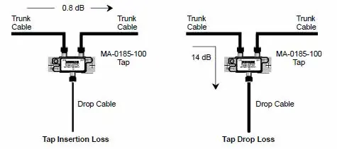
- Taps: Install taps (MA-0185-100) along the trunk cable. Do not use versions earlier than Rev C.
- Splitters: Use splitters (MA-0331-000) to create branches. Only one trunk splitter is allowed per network.
- Cable Lengths: RG6 drop cables must be between 2.5m and 50m. Taps must be spaced at least 2.5m apart.
- Impedance: The network requires 75 Ohm termination. Use dedicated terminators (52-0422-000 for trunk, 52-0402-000 for open drop ports) on all unused ports.
Grounding and Interference
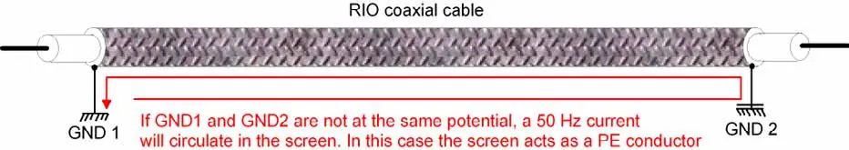
The cable system must be grounded at exactly one point within 6m of the RIO processor. Avoid routing RIO cables near AC/DC power lines. If cables must cross power lines, do so only at right angles. In high-noise environments, use steel conduit.
Optical Fiber Repeaters
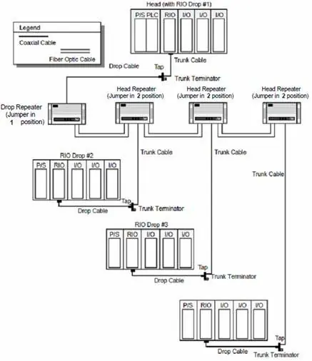
490NRP954 repeaters allow transition between coaxial and fiber media. A maximum of five repeaters can be used in a bus or ring topology. Ensure the NRP chassis is grounded and the jumper switch is set correctly based on whether the unit acts as a drop (position 1) or a head (position 2).
Commissioning
After installation, perform TDR measurements to ensure the total attenuation does not exceed 35dB for copper networks or 11dB for fiber networks. Verify that the trunk cable is grounded at only one point.
Manufacturer information
Schneider Electric
Practical help
Common problems
Communication signal disturbances
Ensure drop cable length is between 2.5m and 50m and taps are spaced at least 2.5m apart.
Excessive communication errors
Do not connect or disconnect drop cables while the network is active.
Network dysfunction
Ensure only one trunk splitter is used per network and all unused ports are terminated with 75 Ohm terminators.
Before use
- Verify that the RIO adapter address is set via rear rotary switches.
- Ensure the network topology matches one of the defined legal configurations.
- Confirm that the cable system is grounded at only one point within 6m of the RIO processor.
- Check that all unused ports are properly terminated with 75 Ohm terminators.
- Ensure power cables are separated from RIO cables to avoid electromagnetic interference.
Specs in practice
- Characteristic Impedance
- 75 Ohms for all RIO cables and components; requires proper matching.
- Maximum Attenuation (Copper)
- Must not exceed 35 dB at 1.544 MHz between head processor and any drop adapter.
- Maximum Attenuation (Fiber)
- 11.0 dB power loss budget for 62.5/125µm multimode fiber.
Images and diagrams
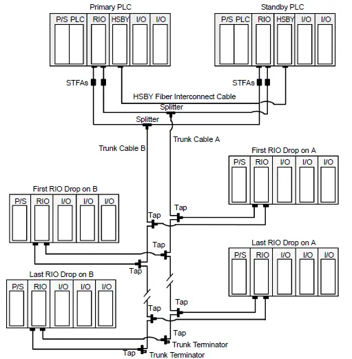
- The manual provides detailed schematics for single cable, dual cable, and Hot Standby (HSBY) topologies.
- Specific diagrams illustrate the correct vs. prohibited routing of RIO cables in metallic cable trays relative to power cabling.
- A diagram shows the insertion and drop loss characteristics of the MA-0185-100 tap.
Model compatibility
- Requires 140CRP93x00 RIO processor as the master node.
- Compatible with 490NRP95400 Optical Fiber Repeaters for network extension.
- Requires specific tap (MA-0185-100 Rev C+) and splitter (MA-0331-000 or MA-0186-100 Rev B+) versions.

Manual page author
David Miller
Documentation analyst
Organizes user manual content into clear summaries, with attention to model details, product context, and everyday usability.