Electronics / Monitors
Installation Guide for Danfoss IPS 8 Extension Module 080G5040
Quick installation and configuration guide for the Danfoss IPS 8 extension module (080G5040). Includes wiring diagrams, relay specifications, and setup instructions for the MCX15B2 controller.
Table of contents
Manual images
Jump to the sectionQuick guide from the manual
The IPS 8 extension module (080G5040) is designed to provide 8 additional digital outputs (purge points) for the IPS system. It must be connected via CANbus to an IPS unit equipped with an MCX15B2 controller. All settings are configured through the main controller.
Installation and Wiring
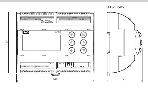
The module is designed for DIN rail mounting. Wiring connections are located on the bottom board:
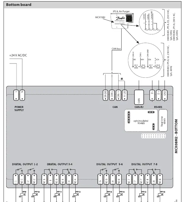
- Power Supply: 2-way screw plug-in connector (pitch 5 mm, cable section 0.2–2.5 mm²). Supports 20–60 V DC and 24 V AC.
- CAN Connector: 4-way screw plug-in connector (pitch 5 mm, cable section 0.2–2.5 mm²).
- Digital Output 1-8: 4-way screw plug-in connector (pitch 5 mm, cable section 0.2–2.5 mm²).
General Features
The device is built for industrial environments with the following specifications:
- Power Supply: 20–60 V DC and 24 V AC ± 15% 50/60 Hz. Maximum consumption 10 W, 17 VA.
- Operating Conditions: -20 to 60 °C (CE) or 0 to 55 °C (UL), 90% RH non-condensing.
- Protection: IP40 on the front cover.
- Housing: DIN rail mounting (EN 60715), self-extinguishing V0 plastic.
Digital Output Specifications
The module features 8 relays with specific load characteristics:
- C1-NO1, C2-NO2: High inrush current (80 A–20 ms) normally open contact relays (16 A).
- C5-NO5, C6-NO6: Normally open contact relays (8 A).
- C3-NO3-NC3, C4-NO4-NC4, C7-NO7-NC7, C8-NO8-NC8: Changeover contacts relays (8 A).
- Total current load limit: 32 A.
Configuration via MCX15B2
All settings are managed via the main controller interface:
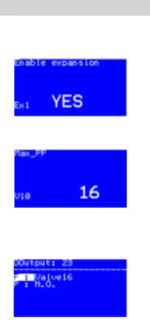
- Activate Expansion Module: Navigate to Main Menu → Start → Main switch OFF → Login (Password 200) → General → Expansion settings → Yes.
- Change Number of Purge Points: Navigate to Main Menu → Start → Main switch OFF → Login (Password 200) → Parameters → Unit config → Valve settings → Max PP.
- Reconfigure Digital Output: Navigate to Main Menu → Start → Main switch OFF → Login (Password 200) → Input/output → I/O Configuration → Valve settings → Digital output → Select output → Assign valve.
Manufacturer information
Danfoss A/S
Practical help
Common problems
Module not recognized or communicating
Ensure the CANbus connection is secure and the module is correctly addressed (ID 125) in the main controller settings.
Digital output not functioning as expected
Verify the configuration in the I/O Configuration menu and ensure the relay load does not exceed the specified limits (e.g., 16A for C1-C2, 8A for others).
Before use
- Verify the power supply is within 20–60 V DC or 24 V AC.
- Ensure the MCX15B2 controller is installed and operational.
- Check that the CANbus wiring is correctly connected to the IPS system.
- Confirm the cable section for connectors is between 0.2–2.5 mm².
Specs in practice
- Total current load limit
- The maximum combined current across all relays must not exceed 32 A.
- High inrush current
- Relays C1 and C2 can handle 80 A for 20 ms, suitable for inductive loads like solenoid coils.
Images and diagrams
- The wiring diagram on page 2 illustrates the connection of the +24 V AC/DC power supply, the CAN bus interface, and the digital output relay connections to the field coils.
Model compatibility
- Requires connection to an IPS system with an MCX15B2 controller.

Manual page author
David Miller
Documentation analyst
Organizes user manual content into clear summaries, with attention to model details, product context, and everyday usability.