General / Other Manuals
Danfoss AK-XM 103A I/O and Communication Module
Technical instructions for the Danfoss AK-XM 103A I/O module, covering installation, wiring, signal types, and technical specifications for refrigeration control systems.
Table of contents
Manual images
Jump to the sectionProduct Overview
The Danfoss AK-XM 103A is a specialized I/O and communication module designed for refrigeration and air conditioning control systems. It provides versatile input and output capabilities to interface with various sensors and actuators. The module features 4 Analog Inputs (AI) and 4 Analog Outputs (AO), allowing for precise monitoring and control of system parameters.
Installation and Safety
Safety is paramount when handling the AK-XM 103A. Always ensure that the power supply is completely disconnected before attempting to add or remove modules from the system. The device is designed for mounting on a standard DIN rail. When installing, ensure the ambient temperature remains within the specified range of -20°C to 55°C (-0°F to 130°F) and that the environment is non-condensing with a relative humidity between 0 and 95%. The module carries an IP10/VBG4 protection rating.
Wiring and Signal Configuration
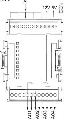
The module supports a wide range of signal types to accommodate different system requirements. Analog inputs can be configured for temperature sensors (Pt 1000), pressure transmitters (such as AKS 32R, AKS 2050, or MBS 8250), voltage signals (0-5V or 0-10V), and digital On/Off signals like door switches or day/night modes. Analog outputs provide a 0-10V signal with a maximum current of 2.5 mA per output. Proper wiring is essential for accurate operation; refer to the terminal mapping to ensure each sensor or actuator is connected to the correct input or output point. The module also provides specific voltage outputs at terminals 9 (12V) and 10 (5V) for powering external sensors.
Galvanic Isolation and Addressing
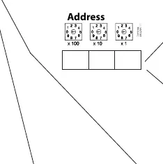
The AK-XM 103A features galvanic isolation between the input and output groups (AI 1-4, AO 1-2, and AO 3-4), which helps protect the controller from electrical interference and potential ground loops. When integrating the module into a larger control network, ensure the address is correctly set using the address switches on the unit. This ensures proper communication between the controller and the I/O module.
Maintenance and Disposal
The module requires minimal maintenance, but it is important to periodically check all terminal connections for tightness and signs of corrosion. As the device contains electrical components, it must not be disposed of with domestic waste. It should be collected separately as electrical and electronic waste in accordance with local and national regulations to ensure environmentally responsible recycling.
Manufacturer information
Danfoss A/S
Practical help
Common problems
Module not communicating
Check the address switch settings and ensure the communication bus is correctly wired.
Inaccurate sensor readings
Verify that the signal type (Pt 1000, 0-10V, etc.) matches the configuration and check for loose terminal connections.
Before use
- Ensure power is disconnected before installation.
- Verify ambient temperature is between -20°C and 55°C.
- Confirm the DIN rail is securely mounted.
- Check that all wiring matches the terminal mapping diagram.
- Verify the address switches are set correctly.
- Ensure the environment is non-condensing.
Specs in practice
- Galvanic isolation
- Electrical separation between AI and AO groups to prevent interference.
Images and diagrams
- The terminal diagram shows the mapping of inputs 1-4 and outputs 1-4 to specific terminal blocks.
- The address section illustrates how to set the module ID using rotary switches.
- The signal table defines which terminal pairs correspond to specific AI and AO points.
Model compatibility
- Compatible with Pt 1000 temperature sensors.
- Supports pressure transmitters like AKS 32R, AKS 2050, and MBS 8250.
- Analog outputs are limited to 2.5 mA per channel.

Manual page author
David Miller
Documentation analyst
Organizes user manual content into clear summaries, with attention to model details, product context, and everyday usability.