Industrial / Cooling Units
User Manual for Seifert 43151001 Control Cabinet Air Conditioner
Quick guide for the Seifert 43151001 control cabinet air conditioner. Includes installation, electrical connection, controller settings, troubleshooting, and maintenance instructions.
Table of contents
Manual images
Click an image to enlargeQuick guide from the manual
This cooling unit is designed for industrial control cabinets. Crucial: After transport, the unit must stand for at least 30 minutes before being connected to the mains to allow compressor oil to flow back. The unit is pre-set to 35°C. Always ensure the air flow is not obstructed and the enclosure is properly sealed to maintain IP54 protection.
Safety Instructions
Only authorized, qualified personnel may work on the unit. Always disconnect the power supply before opening the unit or performing maintenance. The unit must be protected externally from overloading and electrical faults via suitable protective devices. Do not use aggressive cleaning materials.
Functional Principle
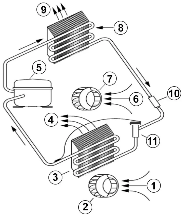
The unit operates on a refrigeration circuit with a compressor, evaporator, condenser, and expansion device using R134a refrigerant. It features two separate air circuits to prevent dirty ambient air from entering the cabinet. Condensation management is handled either via a drain socket or an internal condensate evaporator (depending on the specific model variant).
Technical Data
The unit operates at 120 V ~ 60 Hz with a cooling capacity of 1.63 kW (L35L35). The operating temperature range is +10°C to +55°C. It features an IP54 ingress protection rating and is designed for wall mounting.
Mounting
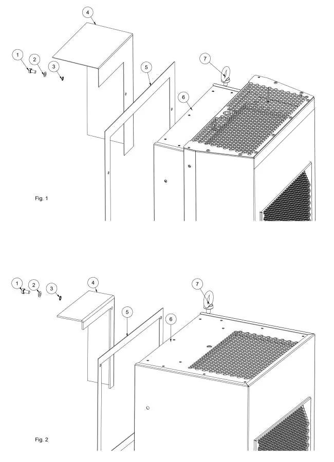
Use the provided 1:1 scale drilling template to prepare the enclosure. Ensure the fixing elements do not interfere with internal equipment. The unit must be installed in the highest possible point of the enclosure. Fit the sealing strip on the cooling unit side connected to the enclosure. Note: For 19" rack mounted units, ignore standard mounting instructions.
Electrical Connection
The unit can be switched on and off via a door contact switch. When delivered, the door contact terminals are bridged. To use a door switch, remove the bridge and connect the switch. Alarm contacts are provided for monitoring; ensure they are not used for fluorescent loads with phase-shifting capacitors.
Controller Settings
The controller display shows temperature and parameter codes. To set the cooling set point (St1): press "SET", use the arrow keys to reach the desired value, and press "SET" again to save. The default is +35°C. To set heating (St2), press "SET" twice. To change system parameters (like temperature units °C/°F or alarm thresholds), press "PRG" for 5 seconds to enter the parameter list.
Taking into Operation
After the 30-minute wait time, connect the unit to the mains. The internal fan will start immediately. If the enclosure temperature exceeds the set point, the compressor and external fan will activate. The system includes minimum ON/OFF times to protect components.
Troubleshooting
If the unit does not cool, verify the power supply, check the St1 setting, ensure the door switch is closed, or check for incorrect phase sequence in the power connector. If the enclosure is too hot, the unit may be undersized or the condenser may need cleaning. Excessive condensate often indicates an open door or damaged sealing strip.
Maintenance & Cleaning
The unit is generally maintenance-free but should be tested functionally every 2,000 hours. If filters are installed, check and clean them regularly. When cleaning the controller panel, use only neutral detergents and water; avoid ethanol, hydrocarbons, or ammonia.
Transport & Storage
Store the unit in its original packaging within a temperature range of -40°C to +70°C. When returning the unit, ensure it is shipped in the same position as it was mounted and protected by shock-resistant padding.
Practical help
Common problems
Unit does not cool
Verify power supply, check St1 setting, ensure door switch is closed, or check phase sequence in the power connector.
Enclosure temperature too hot
Verify if the unit is undersized for the heat load, check if ambient temperature is too high, or clean the condenser.
Excessive condensate
Ensure the enclosure door is closed, check if the IP protection class is below IP54, or repair/replace the sealing strip.
Before use
- Wait at least 30 minutes after transport before connecting to the mains.
- Verify that the power supply rating matches the unit rating plate.
- Ensure air flow (internal and external) is not obstructed.
- Check the 1:1 drilling template dimensions before drilling the enclosure.
- Ensure the enclosure door is closed and sealed properly.
Specs in practice
- Cooling Capacity L35L35
- 1.63 kW cooling power at 35°C ambient and 35°C internal temperature.
- Operating Temperature
- +10°C to +55°C; the range in which the unit functions correctly.
- Ingress Protection
- IP 54; protected against dust ingress and water splashes.
- Voltage / Frequency
- 120 V ~ 60 Hz; ensure your power supply matches this.
Images and diagrams
- The functional principle diagram illustrates the refrigeration circuit components: compressor, evaporator, condenser, and expansion device.
- The mounting diagram shows the difference between recessed and external installation using M6 screws and sealing tape.
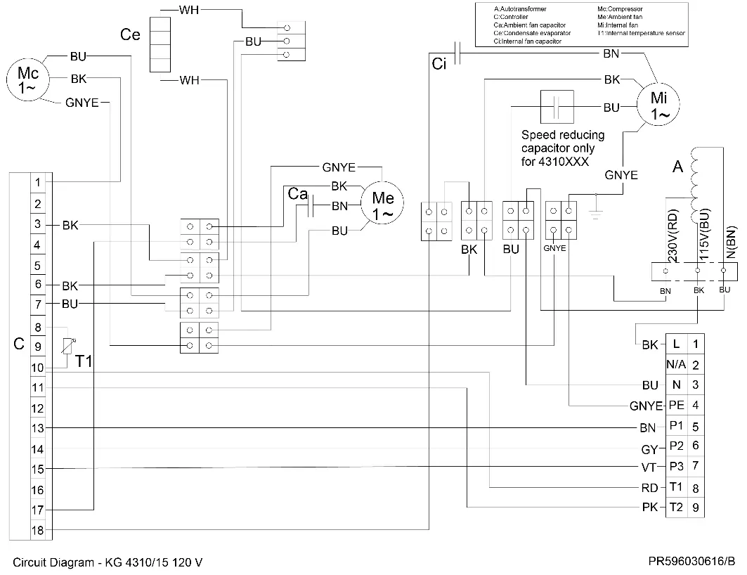
- The wiring diagram details the connections for the power supply, alarm contacts, and door switch.
Model compatibility
- Not intended for household use.
- Designed exclusively for dissipating heat from stationary control cabinets and enclosures.
- Requires external protection via MCB Type D or K.

Manual page author
David Miller
Documentation analyst
Organizes user manual content into clear summaries, with attention to model details, product context, and everyday usability.