HVAC / Heat Pumps
User Manual for Siemens LOGO! Ethernet Programmable Relay
Quick guide for connecting Siemens LOGO! Ethernet programmable relays. Includes HMI settings, LOGO! Soft Comfort software configuration, device address mapping, and Ethernet wiring diagrams.
Table of contents
Manual images
Click an image to enlargeQuick Guide for Siemens LOGO! Ethernet Connection
This document provides instructions for connecting Siemens LOGO! Ethernet programmable relays (series 0BA0, 0BA1, 0BA2, 0BA7, 0BA8) to HMI devices. It covers necessary HMI settings, software configuration using LOGO! Soft Comfort, and device address mapping.
HMI Settings
To establish communication, configure the HMI settings as follows:
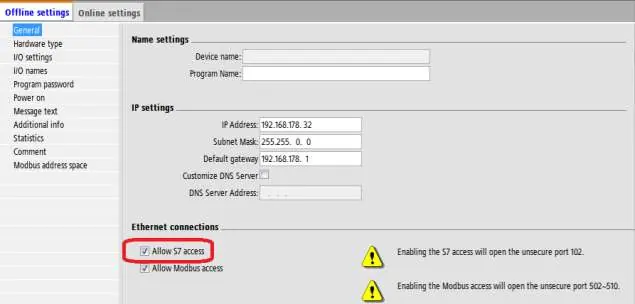
- PLC type: Siemens LOGO (Ethernet)
- PLC I/F: Ethernet
- Port no.: 102
- PLC sta. no.: 1 (Range 1~99)
- Local TSAP: 1000 (Must be greater than 1000)
- Remote TSAP: 2100 (Range 2000~2700)
Note: For OBA2 models, select allow s7 access service; these can also use OBA0/OBA1 models for communication.
Configuring LOGO! Soft Comfort Software
Multi-connection settings require the LOGO! Soft Comfort software to identify connected devices.
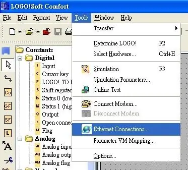
- Open the software and navigate to Tools, then select Ethernet Connections.
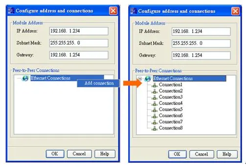
- Right-click on Ethernet Connections and select Add connections. Up to eight connections are supported.
- Double-click on Connection1 and select Server Connection.
- Tick Accept all connection requests to allow connection to any IP.
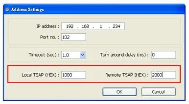
- Set the Remote TSAP to 10.00.
- Repeat the process for connections 2 through 8.
- Complete the settings and download the connection configuration to the Siemens LOGO! device.
Note: The values for Local TSAP and Remote TSAP must be set oppositely in EasyBuilder for successful communication.
Device Address Mapping
The manual provides detailed address mapping tables for various device types including I, Q, M, AI, AQ, AM, NI, NAI, NQ, and NAQ. Refer to the specific tables for LOGO! 0BA7 and LOGO! 0BA0/0BA8 to identify the correct VM (Virtual Memory) addresses and ranges for your specific hardware version.
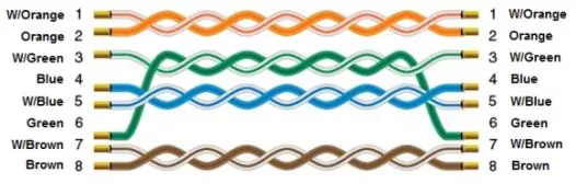
Wiring Diagram
The Ethernet cable wiring follows standard color-coding. Ensure the cable is correctly terminated according to the standard RJ45 pinout diagram provided in the manual.
Manufacturer information
Siemens AG
Practical help
Common problems
Communication failure
Ensure that the Local TSAP and Remote TSAP values are set oppositely in EasyBuilder.
Connection limit reached
The system supports a maximum of eight connections.
Before use
- Ensure LOGO! Soft Comfort software is installed on your computer.
- Verify your specific Siemens LOGO! model (0BA0, 0BA1, 0BA2, 0BA7, or 0BA8).
- Prepare a standard Ethernet cable for connection.
- Ensure the HMI and PLC are on the same network segment.
Images and diagrams
- The Ethernet cable diagram illustrates the standard color-coded pinout for RJ45 connectors.
Model compatibility
- Supports Siemens LOGO! series: 0BA0, 0BA1, 0BA2, 0BA7, and 0BA8.

Manual page author
David Miller
Documentation analyst
Organizes user manual content into clear summaries, with attention to model details, product context, and everyday usability.