Smart Home / Smart Plugs & Strips
User Guide for Schneider Electric ULP System
Comprehensive user guide for the Schneider Electric ULP (Universal Logic Plug) system. Includes installation, connection rules, architecture design, and technical specifications for ULP modules and accessories.
Table of contents
Manual images
Click an image to enlargeQuick guide from the manual
The ULP (Universal Logic Plug) system is designed to integrate metering, communication, and operating assistance functions for Schneider Electric circuit breakers. An Intelligent Modular Unit (IMU) consists of a main device (circuit breaker or switch) with an internal communication module and one or more external ULP modules. This guide provides the necessary rules for composition, connection, power supply, and network architecture design.
ULP System Overview
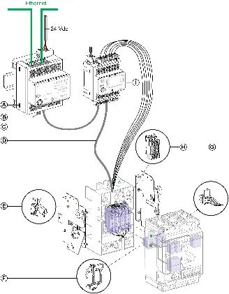
The ULP system enhances the functionality of PowerPacT and MasterPacT circuit breakers. Key components include:
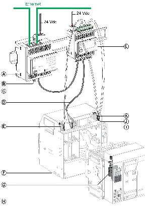
- IFE Ethernet Interfaces: Provide Ethernet access for remote monitoring.
- IFM Modbus-SL Interfaces: Provide Modbus serial line access.
- IO Modules: Offer digital inputs/outputs for cradle management and custom applications.
- FDM121 Display: Provides local display of measurements and alarms.
- UTA Tester: Used for setup, testing, and maintenance.
Connection and Power Supply Rules
Proper installation is critical for system integrity:
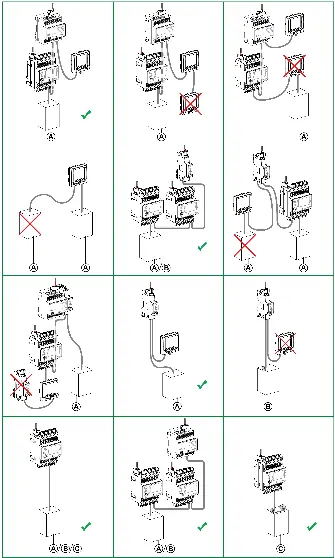
- Daisy-Chaining: ULP modules are connected in a daisy chain using RJ45 ULP cords.
- Line Termination: A ULP line termination (TRV00880) must be installed on the unused RJ45 port at the end of the ULP line.
- Cable Lengths: Maximum length between two ULP modules is 5 m (without external power) or 10 m (with external power). Total length per IMU is 20 m.
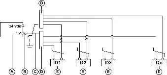
- Power Supply: The system requires a 24 Vdc SELV power supply. Load balance must be calculated based on the consumption of all connected ULP modules.
- Earthing: Ensure proper protective and functional grounding of the enclosure and DIN rails.
Communication Network Setup
The system supports both Modbus-SL and Ethernet networks:
- Modbus-SL: Requires specific wiring for D0, D1, and 0 VL signals. Use Modbus line termination at both ends of the network.
- Ethernet: Uses Category 5e or 6 SFTP cables. No maximum number of devices per network, but transmission rates are 10-100 Mbps.
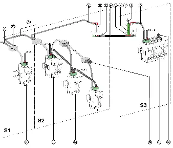
System Architectures
The ULP system can be configured in several ways:
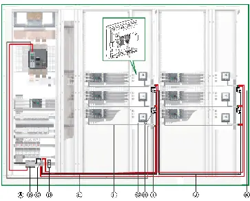
- Standalone: No communication interface.
- Centralized Modbus: IFE servers and IFM interfaces are grouped in islands.
- Distributed Modbus: IFM interfaces are distributed near the ULP modules.
- Ethernet Architectures: Supports both star and daisy-chain topologies for high dependability or competitive cost.
Technical Characteristics
The system operates within specific environmental and electrical limits. Always verify firmware and hardware compatibility using the EcoStruxure Power Commission software. Refer to the appendices for detailed part numbers and technical specifications of all ULP components.
Manufacturer information
Schneider Electric
Practical help
Common problems
Voltage drop on ULP network
Calculate load balance, increase power supply cable cross-section, or add a loop to the power supply from the last device.
Communication failure
Verify Modbus line termination is installed at both ends of the network and check wiring continuity.
Firmware/Hardware incompatibility
Use EcoStruxure Power Commission software to perform diagnostics and identify recommended corrective actions.
Before use
- Verify circuit breaker compatibility with the ULP system.
- Ensure the 24 Vdc power supply is SELV compliant.
- Check that all ULP cords are within the maximum allowed length.
- Install a ULP line termination on the last module in the ULP line.
- Ensure proper earthing of the enclosure and DIN rails.
Specs in practice
- ULP Line Termination
- A passive component required at the end of the ULP line to prevent signal reflection.
Images and diagrams
- Wiring diagrams are provided for various architectures, including centralized Modbus and distributed Modbus setups.
- Diagrams illustrate the correct connection of 24 Vdc power supply and Modbus communication cables.
Model compatibility
- UTA tester is only compatible with PowerPacT H-, J-, and L-frame circuit breakers.
- EIFE interface is specific to MasterPacT MTZ drawout circuit breakers.
- IFM interface LV434000 replaces the older STRV00210.

Manual page author
David Miller
Documentation analyst
Organizes user manual content into clear summaries, with attention to model details, product context, and everyday usability.