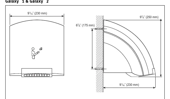
Home Appliances / Hand Dryers
Stiebel Eltron Galaxy Hand Dryer Operation and Installation Manual
Quick guide for the Stiebel Eltron Galaxy series automatic hand dryer. Includes installation steps, electrical requirements, safety warnings, and maintenance instructions.
Table of contents
Manual images
Click an image to enlargeQuick guide from the manual
The Stiebel Eltron Galaxy series is an automatic, touchless hand dryer. To operate, shake off excess water, place hands 4 to 7 inches underneath the unit, and rub them together. The unit will dry hands in approximately 25 to 35 seconds and shut off automatically 7 seconds after hands are removed. Ensure the sensor (black rectangle between air grills) is kept clean and free of obstructions.
Safety instructions
DANGER: Electrocution. Before any installation, adjustment, or service, turn off all circuit breakers and disconnect switches. The unit must be properly grounded. Never remove the cover while electricity is connected.
WARNING: Fire. Do not install the unit in rooms with fire/explosion risks (chemicals, dust, gases). Do not install near flammable materials or pipes. Do not use with solid-state speed control devices.
WARNING: Injury. Children or persons with limited capabilities must be supervised when using the appliance.
Appliance description and operation
The unit features an infrared sensor switch. If the sensor is covered by dirt or gum, the unit will not operate properly. If the unit overheats, a safety high-limit switch will turn off the heating element; it resets automatically once cooled.
Installation
Preparation: The unit requires an independent circuit with a 3-wire cable protected by a double-pole circuit breaker. Galaxy 1/M1 (120V) requires a 20A breaker and AWG 12 copper wire. Galaxy 2/M2 (208-240V) requires a 15A breaker and AWG 12 copper wire.
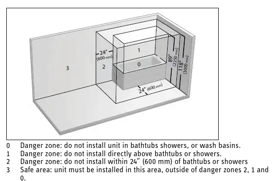
Minimum Clearances: Do not install in danger zones 0, 1, or 2 (bathtubs, showers, or wash basins). Install at least 4 inches from perpendicular walls and at least 12 inches above countertops to avoid splashing. The unit must be mounted at least 48 inches above the floor.
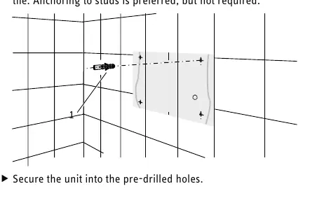
Wall Mounting: Use the provided drilling template to mark mounting points. Secure the unit into the wall using anchors suitable for the surface (drywall or tile). Pull down the locking slide to remove the front cover for access to mounting holes and electrical connections.
Cleaning and maintenance
Clean the case using a soft cloth and mild detergent. Never use abrasive cleaners as they will scratch the finish. Do not spray water or cleaning fluids directly onto the unit. Ensure the electric eye switch is not covered during cleaning.
Technical data
Galaxy 1 and M1 operate at 120V (1850W). Galaxy 2 and M2 operate at 208V or 240V (1500W or 2000W). All models feature a sound level of 53 dB(A) and an automatic drying time of 30 seconds.
Warranty
The product includes a 5-year residential and commercial warranty against defects in workmanship and materials. Warranty is void if the unit is installed or used improperly, or if the design is altered. For service or questions, contact technical support at 800.582.8423.
Practical help
Common problems
Unit does not run
Check if the infrared sensor (black rectangle) is covered by dirt or gum. Clean the sensor area.
Unit overheats
The safety high-limit switch has activated. It will reset automatically once the heating element cools down.
Unit splashes water
Ensure the unit is not installed in danger zones 0, 1, or 2 (near bathtubs or showers) and is at least 12 inches above countertops.
Before use
- Ensure the main breaker panel switch is OFF before starting installation.
- Verify the circuit is independent and uses a 3-wire cable.
- Confirm the installation location is not in a danger zone (0, 1, or 2).
- Ensure the unit is mounted at least 48 inches above the floor.
- Check that the air inlet and outlet grills are free of obstructions.
Specs in practice
- Galaxy 1 / M1 Electrical
- 120V, 1850W, requires 20A circuit breaker and AWG 12 copper wire.
- Galaxy 2 / M2 Electrical
- 208V/240V, 1500W/2000W, requires 15A circuit breaker and AWG 12 copper wire.
Images and diagrams
- Minimum clearances diagram illustrates danger zones 0, 1, and 2 where installation is prohibited.
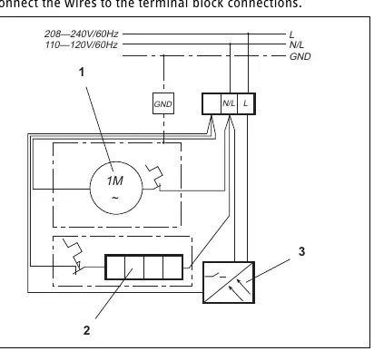
- Wiring diagram shows the connection points for the fan motor, heating element, and sensor.
Model compatibility
- Do not use with any solid-state speed control device.
- Requires a double-pole circuit breaker.
- Copper wire must be used for electrical connections.

Manual page author
David Miller
Documentation analyst
Organizes user manual content into clear summaries, with attention to model details, product context, and everyday usability.