Home Appliances / Hand Dryers
Installation and Wiring Instructions for Vent-Axia 1.0kW Automatic Hand Dryer
Quick guide for the Vent-Axia 1.0kW Automatic Hand Dryer. Includes installation steps, wiring diagrams, maintenance, troubleshooting, and sensor/air speed adjustments.
Table of contents
Manual images
Click an image to enlargeQuick Guide
This manual provides installation and maintenance instructions for the Vent-Axia 1.0kW Automatic Hand Dryer. The unit is designed for commercial use and requires installation by a qualified electrician. Key features include no-touch operation, adjustable air speed, and an integrated LED status indicator.
Safety Information
WARNING: This product is not for household use and must be installed by a qualified service person. Disconnect power at the service breaker before installing or servicing to avoid electrical shock or burns.
- Use 2.0 mm² (AWG No. 14) solid conductor for wiring.
- All units must be supplied with a 3-wire service.
- The ground wire must be connected to the dryer's backplate.
- Do not install the dryer directly above a basin if reflection might trigger the sensor.
Installation
- Ensure the power supply breaker is switched off.
- Place the mounting template against the wall at the desired height and mark the 4 mounting holes and wire service entry.
- Loosen the middle screw and remove the unit from the plugin base plate.
- Remove the two screws from the Wago connector on the base plate.
- Run the power cable through the base plate, connect it to the Wago connector, and fasten the connector back to the plate.
- Fix the base plate to the wall using 4 screws (1/4 x 1-3/4").
- Mount the unit onto the base plate and tighten the middle screw.
Operation
The dryer features no-touch operation. Simply place hands under the outlet to start the drying cycle. The unit will stop automatically once hands are removed.
Adjustments
To adjust settings, switch off the power, loosen the cover screws, and remove the cover.
- Air Speed: Use a small Phillips head screwdriver or flat blade probe to turn the VR shaft. Turn clockwise (CW) to increase power or counter-clockwise (CCW) to reduce power.
- Sensor Range: The standard setting is 6.69" (170 mm ± 20 mm). Turn clockwise to increase the sensing range or counter-clockwise to decrease it. Do not overturn the adjustment screw.
Cleaning and Maintenance
Periodic cleaning is recommended for optimum performance:
- Disconnect the electrical supply.
- Remove the cover.
- Clean all dust and lint from the interior.
- Wipe the cover with a damp cloth and mild cleaning solution. Do not use abrasives.
- Do not flush the unit with water.
- Replace the cover and do not over-tighten the screws.
Diagnostics and Remedies
If the dryer fails to operate, check the following:
- Dryer will not run: Ensure the breaker is operational. Check connections at the terminal block.
- Dryer cycles by itself: Check for obstructions on or in front of the IR sensor. Clean the sensor lens.
- Loud noise/no run: Verify input voltage. If the problem persists, the CBM, IR sensor, or VR component may need replacement.
- Low air pressure: Check for dust/lint buildup in intake vents.
Smart LED Indicator
The LED indicator displays the status of the hand dryer:
- WHITE: Hand dryer ready.
- GREEN: Hand dryer in use.
- RED: Replace HEPA filter.
- BLUE: Replace motor brushes.
Practical help
Common problems
Dryer will not run
Ensure the breaker is on, check power connections, and verify the sensor lens is clean and free of obstructions.
Dryer cycles by itself
Check for obstructions in front of the IR sensor and clean the sensor lens.
Dryer makes loud noise or does not run
Verify input voltage. If voltage is correct, the CBM, IR sensor, or VR component may be damaged.
Low air pressure
Check for dust or lint buildup in the intake vents and clean if necessary.
Before use
- Ensure power supply breaker is switched off.
- Verify 3-wire service is available.
- Use 2.0 mm² (AWG No. 14) solid conductor for wiring.
- Ensure installation is performed by a qualified electrician.
- Check mounting height recommendations (e.g., 1000mm for Men, 960mm for Women).
Specs in practice
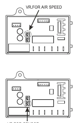
- VR for Sensor
- Variable Resistor used to adjust the infrared sensor detection range.
- VR for Speed
- Variable Resistor used to adjust the air speed of the motor.
Images and diagrams
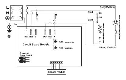
- Circuit Diagram: Illustrates the wiring connections for L, N, and Ground, including the sensor module and motor.
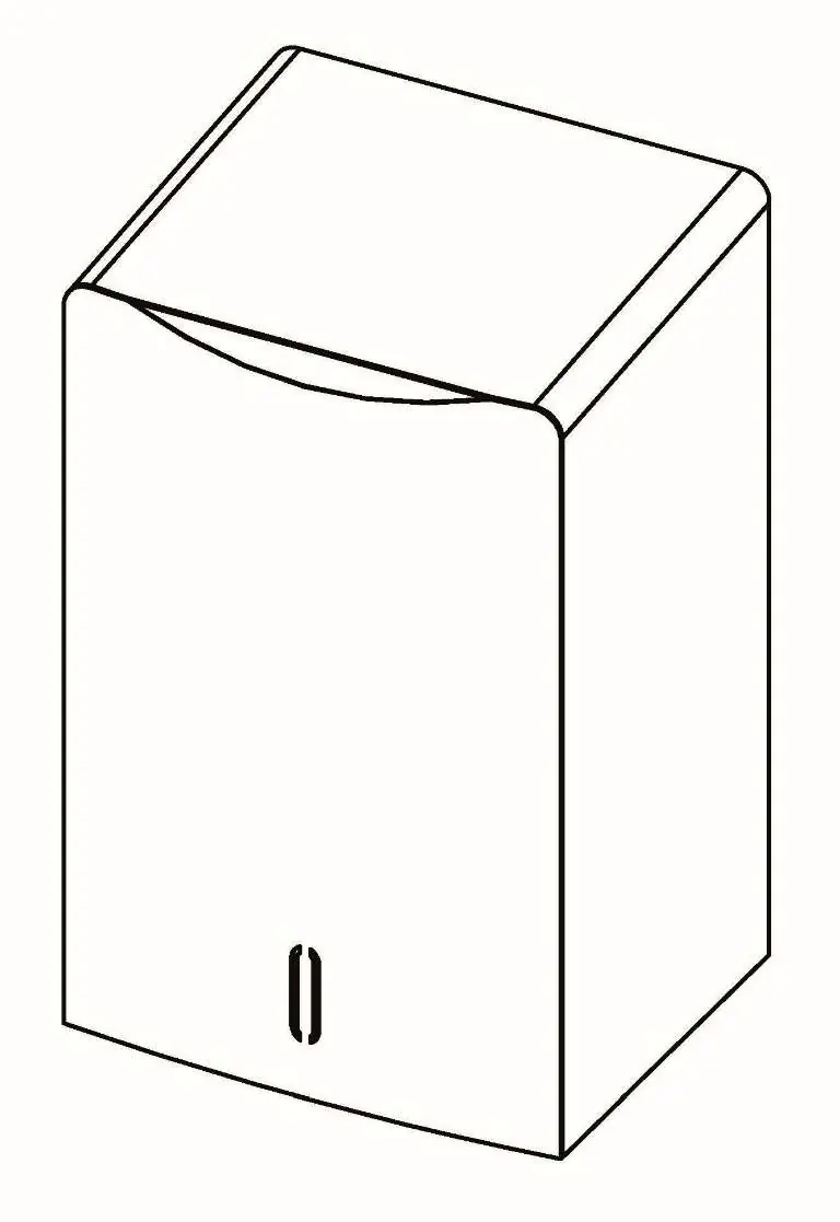
- Installation Steps: Shows the process of removing the unit from the base plate, wiring the Wago connector, and mounting the base plate to the wall.
Model compatibility
- Not for household use.
- Do not install directly above a basin if reflection might occur.
- Requires 3-wire service.

Manual page author
David Miller
Documentation analyst
Organizes user manual content into clear summaries, with attention to model details, product context, and everyday usability.