Computers / Server Chassis
Supermicro SuperServer 221H-TN24R Quick Reference Guide
Quick reference guide for the Supermicro SuperServer 221H-TN24R, covering CPU installation, memory population, board layout, and system setup.
Quick answers from the manual
Quick answer
- This guide provides installation and configuration steps for the Supermicro SuperServer 221H-TN24R, including CPU installation, memory population, and cable routing. p. 1
Key actions
- Install CPU using T30 Torx driver with 12lbf-in torque. p. 1
- Populate memory according to the DDR5 population table. p. 1
First start
- Check the BMC password on the chassis sticker. p. 1
- Ensure all power supplies have the same power output. p. 1
Show 4 more answers Show less
Problems and fixes
PSU failure or warning
Check LED status: Solid Amber indicates failure or invalid source; Blinking Amber indicates a warning.
p. 1Maintenance and reset
- Reset BMC password using the Supermicro IPMICFG tool. p. 1
Technical specifications
| Parameter | Value | Meaning | Pages |
|---|---|---|---|
| Power Supply | 1200W Titanium | Redundant power supply unit rating. | p. 1 |
Where to find it in the PDF
- Quick Reference Guide p. 1
Table of contents
Manual images
Click an image to enlargeQuick Guide from the Manual
This document serves as a quick reference for the Supermicro SuperServer 221H-TN24R. It provides essential information for hardware installation, including CPU and memory configuration, board layout, and cable routing. Always ensure all power supplies have the same power output before connecting the system to power.
CPU Installation
Follow these steps to install the processor:
- Prepare the bracket: Put the processor into the bracket, paying attention to the lineup pin and key on both the processor and the carrier.
- Assemble: Place the processor carrier module into the heatsink.
- Install: Place the processor heatsink module into the motherboard. Use a T30 Torx driver and apply a torque of 12lbf-in to the threaded fasteners.
Memory Population
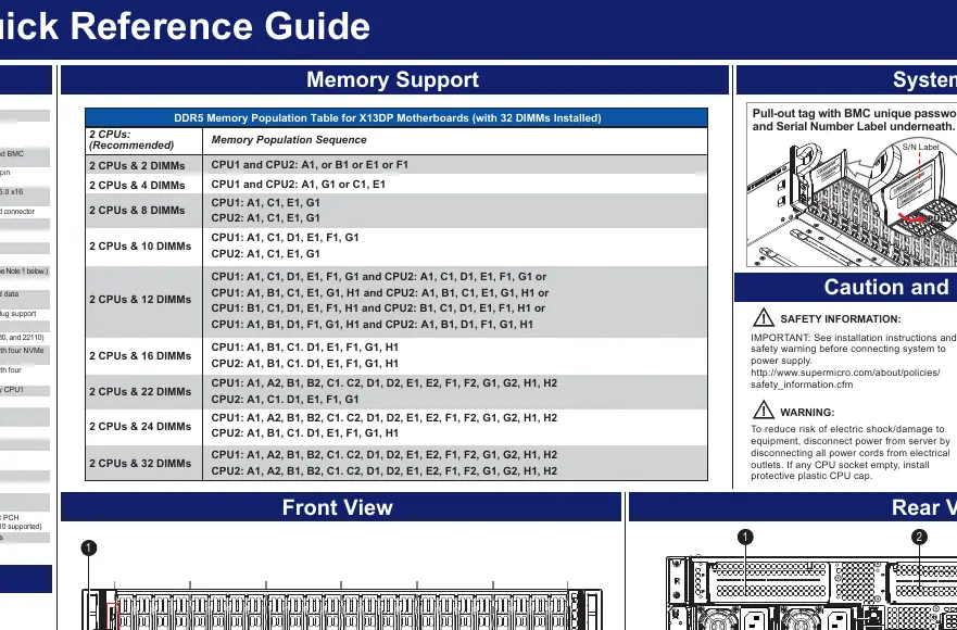
The system supports DDR5 memory. Population depends on the number of CPUs and DIMMs installed. For 2 CPUs (Recommended), follow the specific population sequence provided in the memory table, which ranges from 2 DIMMs up to 32 DIMMs.
Board Layout and Connectors
The motherboard features various connectors, including:
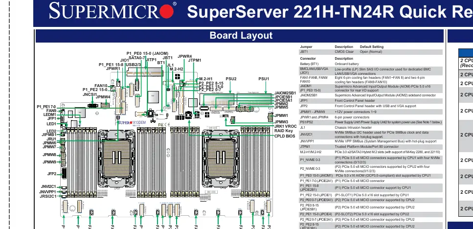
- FAN1-FAN10: Cooling fan headers.
- JFP1/JFP2: Front control panel headers.
- JPMW1-JPMW9: +12V power connectors.
- M.2-H1/M.2-H2: Hybrid M.2 slots (PCIe 3.0 x2/SATA3).
- P1_NVME/P2_NVME: PCIe 5.0 x8 MCIO connectors for NVMe drives.
- JBT1: CMOS clear jumper.
System Information and BMC
Each system includes a unique default password for the ADMIN user, located on a sticker on the motherboard and underneath the service tag on the chassis. If necessary, the password can be reset using the Supermicro IPMICFG tool.
Cable Routing
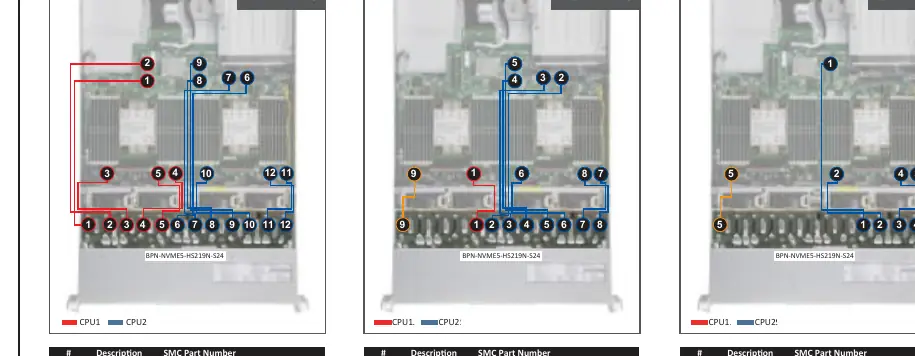
The manual provides specific routing diagrams for:
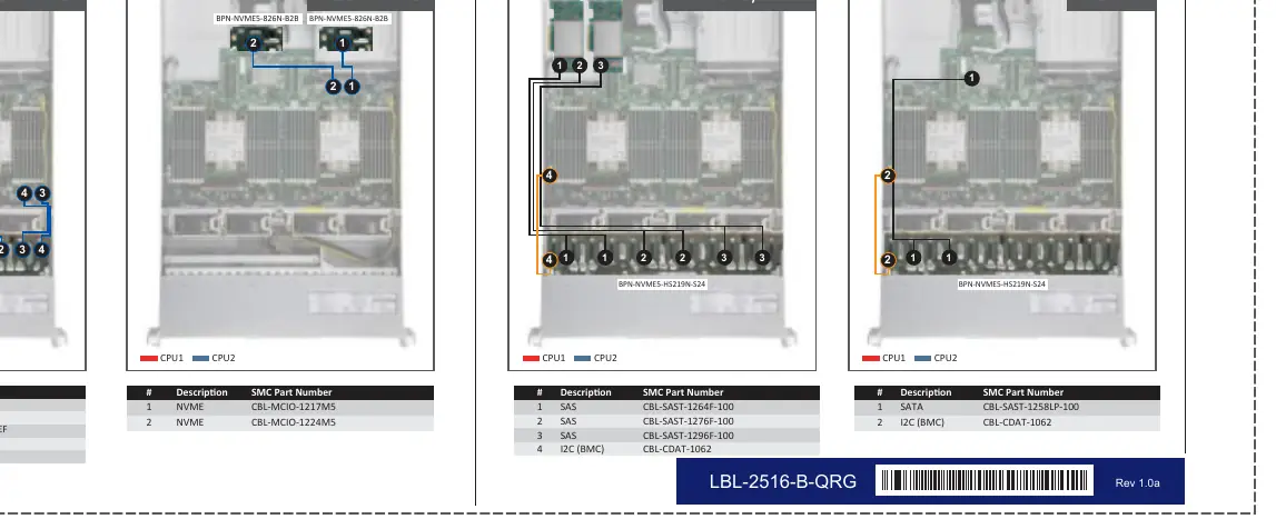
- NVMe Drive Bay: Configurations for 24 NVMe, 16 NVMe, 8 NVMe, and Rear NVMe.
- Storage AOC: Cable routing for 16+8 SAS/SATA and 8 SATA configurations.
Rear View and Power
The rear panel includes:
- PCIe Slots: Various PCIe 5.0 x8 and x16 slots.
- Networking: AIOM/OCP 3.0 networking slots.
- Power Supplies: Redundant 1200W Titanium power supplies.
- LED Indicators: Power supply LEDs indicate operational status (Solid Green), standby (Blinking Green), or warnings (Amber).
Manufacturer information
Super Micro Computer, Inc.
Practical help
Common problems
System will not operate
Ensure all installed power supplies have the same power output. Mixed power supplies are not supported.
Unknown BMC password
Check the sticker on the motherboard or the sticker underneath the service tag on the chassis.
Power supply warning
If the LED is blinking amber, a PSU warning event has occurred; if solid amber, the PSU is disconnected, invalid, or has failed.
Before use
- Verify all power supplies have the same power output.
- Ensure CPU socket has a protective plastic cap if empty.
- Check BMC password on the chassis sticker.
- Use a T30 Torx driver for heatsink installation.
- Ensure correct torque of 12lbf-in for heatsink fasteners.
Show more Show less
Specs in practice
- 1200W Titanium
- Rating of the redundant power supply units.
Images and diagrams
- CPU Installation: Shows the alignment of the processor key with the carrier and the heatsink fastening sequence.
- Memory Population Table: Defines the slot sequence for 2 to 32 DIMMs.
- Cable Routing: Diagrams for NVMe and SAS/SATA drive bay configurations.
Model compatibility
- Slot 6 is disabled if Slot 5 is configured as x16.
- Slot 8 is disabled if Slot 7 is configured as x16.

Manual page author
Michael Turner
Technical manual editor