Automotive / Security Systems
User Manual for Teltonika FMC003 Advanced OBDII Tracker
Quick guide for the Teltonika FMC003 Advanced OBDII Tracker. Learn how to install the SIM card, connect the battery, configure via SMS or PC, and understand LED status indicators.
Table of contents
Manual images
Click an image to enlargeQuick guide from the manual
The Teltonika FMC003 is an advanced OBDII tracker designed for vehicle monitoring. This guide provides essential steps for installation, configuration, and operation. Always ensure the vehicle ignition is off before mounting or unmounting the device.
Device Overview
The device features an OBDII connector for vehicle integration, a micro-SIM slot, and a battery socket. Two LEDs (Navigate and Status) provide visual feedback on the device's operational state.
Installation
To set up the device, you must first access the internal components:
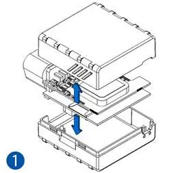
- Cover Removal: Gently remove the FMC003 cover using a plastic pry tool from both sides.
- SIM Card Insertion: Insert the Micro-SIM card into the slot. Ensure the cut-off corner is pointing forward toward the slot. If the SIM has a PIN request, it must be disabled or configured later via the Teltonika Configurator.
- Battery Connection: Connect the internal battery to the socket. Position the battery so it does not obstruct other components.
- Closing: Attach the device cover back securely.
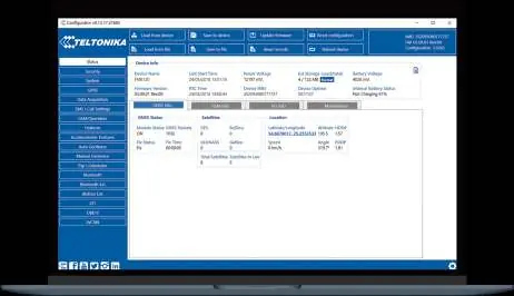
PC Connection and Configuration
The device can be configured using a Windows PC:
- Power-up: Connect the device to a 10–30 V DC power supply using the supplied cable.
- Connection: Connect to the PC via Micro-USB cable or Bluetooth.
- Bluetooth Pairing: The device is discoverable as "FMC003_last_7_imei_digits". The default password is 5555.
- Software: Download and install the Teltonika Configurator. Ensure the required MS .NET Framework (4.6.2) is installed on your Windows system.
SMS Configuration
You can configure the device remotely by sending an SMS command. Note that two space symbols must be inserted before the SMS text.

Command format: setparam 2001:APN;2002:APN_username;2003:APN_password;2004:Domain;2005:Port;2006:0
- 2001: APN
- 2002: APN username
- 2003: APN password
- 2004: Server Domain
- 2005: Server Port
- 2006: Data sending protocol (0 for TCP, 1 for UDP)
LED Indications
The device uses two LEDs to indicate status:
- Navigation LED: Permanently on indicates no GNSS signal. Blinking every second indicates normal mode with GNSS working. Fast blinking indicates firmware flashing.
- Status LED: Blinking every second indicates normal mode. Blinking every two seconds indicates sleep mode. Fast blinking indicates modem activity.
Technical Specifications
- Input Voltage: 10–30 V DC with overvoltage protection.
- Internal Battery: 170 mAh Li-Po battery (3.7 V).
- Operating Temperature: -40 °C to +85 °C (without battery).
- Ingress Protection: IP41.
- Dimensions: 67.2 x 49.6 x 25 mm.
Safety Information
The device is susceptible to water and humidity. Do not disassemble the device if damaged. Ensure the device does not interfere with the driver's operation or distract the driver. Dispose of batteries according to local regulations; do not mix with household waste.
Practical help
Common problems
Device not connecting to PC
Install the required USB drivers from the Teltonika website or ensure Bluetooth is enabled on your PC (default password 5555).
SIM card not detected
Ensure the SIM card is inserted with the cut-off corner pointing forward toward the slot.
Device not powering on
Verify the vehicle ignition is on (13.2–30V) or check if the internal battery is properly connected.
Before use
- Ensure you have a micro-SIM card with PIN request disabled.
- Download and install the Teltonika Configurator software.
- Verify your vehicle's OBDII connector location.
- Ensure you have a plastic pry tool for opening the device cover.
Specs in practice
- Input voltage
- 10–30 V DC with overvoltage protection.
- Operating temperature
- -40 °C to +85 °C (without battery).
- Internal battery
- 170 mAh Li-Po battery 3.7 V.
- Ingress Protection
- IP41 (susceptible to water and humidity).
Images and diagrams
- The device features an OBDII connector, status LEDs, a micro-SIM slot, and a battery socket.
- The pinout diagram details the 16-pin OBDII connector layout.
Model compatibility
- Compatible with Windows OS for configuration.
- Supports various OBD protocols including ISO 9141-2, ISO 14230-4, and ISO 15765-4.

Manual page author
Michael Turner
Technical manual editor
Reviews PDF manuals for structure, safety notes, and practical product details so readers can find the right information quickly.