Plumbing / Bathroom Accessories
User Manual for 2.5G SFP Fiber Optic Converter
Quick guide for the 2.5G SFP Fiber Optic Converter. Learn how to install, connect fiber and Ethernet cables, understand LED indicators, and check technical specifications.
Quick answers from the manual
Quick answer
- This device converts 2.5G/1.25G fiber signals to 10/100/1000M/2.5G electrical signals. Installation involves connecting the power adapter, inserting the SFP module, connecting the Ethernet cable, and setting the TX/RX switch. p. 1, 2
Key actions
- Install the SFP module and fiber cable. p. 2
- Connect the Ethernet cable. p. 2
First start
- Connect power adapter, insert SFP module, connect Ethernet cable, set TX/RX switch, turn on power. p. 2
Technical specifications
| Parameter | Value | Meaning | Pages |
|---|---|---|---|
| Power Supply | DC 5V/1A | Required power input | p. 3 |
| Operating Temp | 0°C ~ 50°C | Safe operating temperature range | p. 3 |
Where to find it in the PDF
- Product Introduction p. 1
- Installation p. 2
- Technical Specs p. 3
Table of contents
Quick Guide
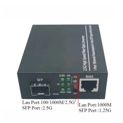
This 2.5G SFP Fiber Optic Converter is designed to convert 2.5G/1.25G fiber signals into 10/100/1000M/2.5G electrical signals. It supports auto-negotiation and is a plug-and-play device, making it suitable for long-distance network extensions.
Package Contents
- 1x 2.5G SFP Fiber Optic Converter
- 1x DC Power Adapter
Quick Installation
- Power Preparation: Connect the power adapter to the device, but do not turn on the power yet.
- Fiber Connection: Insert a compatible SFP optical module into the SFP port and connect your fiber cable to the module.
- Electrical Connection: Plug a Cat5e or Cat6 Ethernet cable into the RJ45 port and connect the other end to your network device.
- Configuration & Power: Set the TX/RX switch to the correct mode for your setup, then turn on the power switch.
- Status Check: Confirm the PWR LED is solid green to verify the device is powered on.
LED Indicator Guide
The device features several LED indicators to help monitor status:
- PWR: Solid Green indicates normal power.
- 2.5G: Solid Green indicates a 2.5G link is established (SFP).
- 1G: Solid Green indicates a 1G link is established (SFP).
- FX: Blinking Green indicates fiber data transmission is active.
- SPEED: Blinking Green indicates RJ45 port data transmission is active.
Technical Specifications
- RJ45 Port: 10/100/1000M/2.5G (auto-negotiation)
- SFP Port: 2.5G/1.25G (compatible with standard SFP modules)
- Transmission Distance: RJ45: 100m (Cat5e/Cat6); Fiber: Depends on SFP module
- Power Supply: DC 5V/1A
- Operating Temperature: 0°C ~ 50°C
- Dimensions: 100 x 80 x 30 mm
Manufacturer information
The Home Depot
Practical help
Common problems
Device does not power on
Ensure the power adapter is securely connected and the power switch is in the ON position.
No network link established
Verify that the SFP module is compatible and fully inserted, and check that the fiber cable is properly connected.
Before use
- Ensure you have a compatible SFP optical module.
- Verify the power adapter (DC 5V/1A) is available.
- Have a Cat5e or Cat6 Ethernet cable ready.
- Ensure the operating environment is between 0°C and 50°C.
Specs in practice
- Power Supply
- Requires a DC 5V/1A power input.
Images and diagrams
- The front panel features an SFP port on the left and an RJ45 port on the right.
- A TX/RX switch is located between the LED indicators and the RJ45 port.
- LED indicators are grouped in the center to show power, link, and data transmission status.
Model compatibility
- RJ45 port supports Cat5e/Cat6 cables up to 100m.
- Fiber transmission distance depends on the specific SFP module used.

Manual page author
Emily Carter
User documentation editor
Prepares concise manual descriptions and highlights the most useful setup, operation, and maintenance information for readers.