Furniture / Bedroom Furniture
Assembly Instructions for Tribesigns 2-Tier Bar Unit
Comprehensive assembly guide for the Tribesigns 2-Tier Bar Unit. This manual includes a complete parts list, hardware identification, detailed step-by-step installation instructions, and essential tips for proper assembly.
Quick answers from the manual
Quick answer
- This document is the assembly manual for the Tribesigns 2-Tier Bar Unit. It provides a parts list, hardware list, and 20 steps to assemble the furniture. p. 1, 4, 5, 6
Key actions
- Assemble on a soft surface to avoid scratches. p. 3
- Use hand tools; avoid high-torque electric screwdrivers. p. 3, 7
Problems and fixes
Plastic part for cam/pin won't press in
Loosen the screw counter-clockwise or remove it, press the plastic part in, then tighten the screw clockwise.
p. 7Where to find it in the PDF
- Parts List p. 4, 5
- Hardware List p. 6
- Assembly Steps p. 8, 17
Table of contents
Manual images
Click an image to enlargeQuick Guide from the Manual
Before beginning assembly, please review these essential tips to ensure a smooth process:
- Check Parts: Verify all parts against the parts list before starting.
- Assembly Surface: Assemble the unit on a soft, smooth surface (like a rug) to prevent scratches.
- Tools: Hand tools are recommended. If using an electric screwdriver, reduce power and torque to avoid damaging the product.
- Alignment: Do not fully tighten screws until all parts are confirmed in place to avoid misalignment.
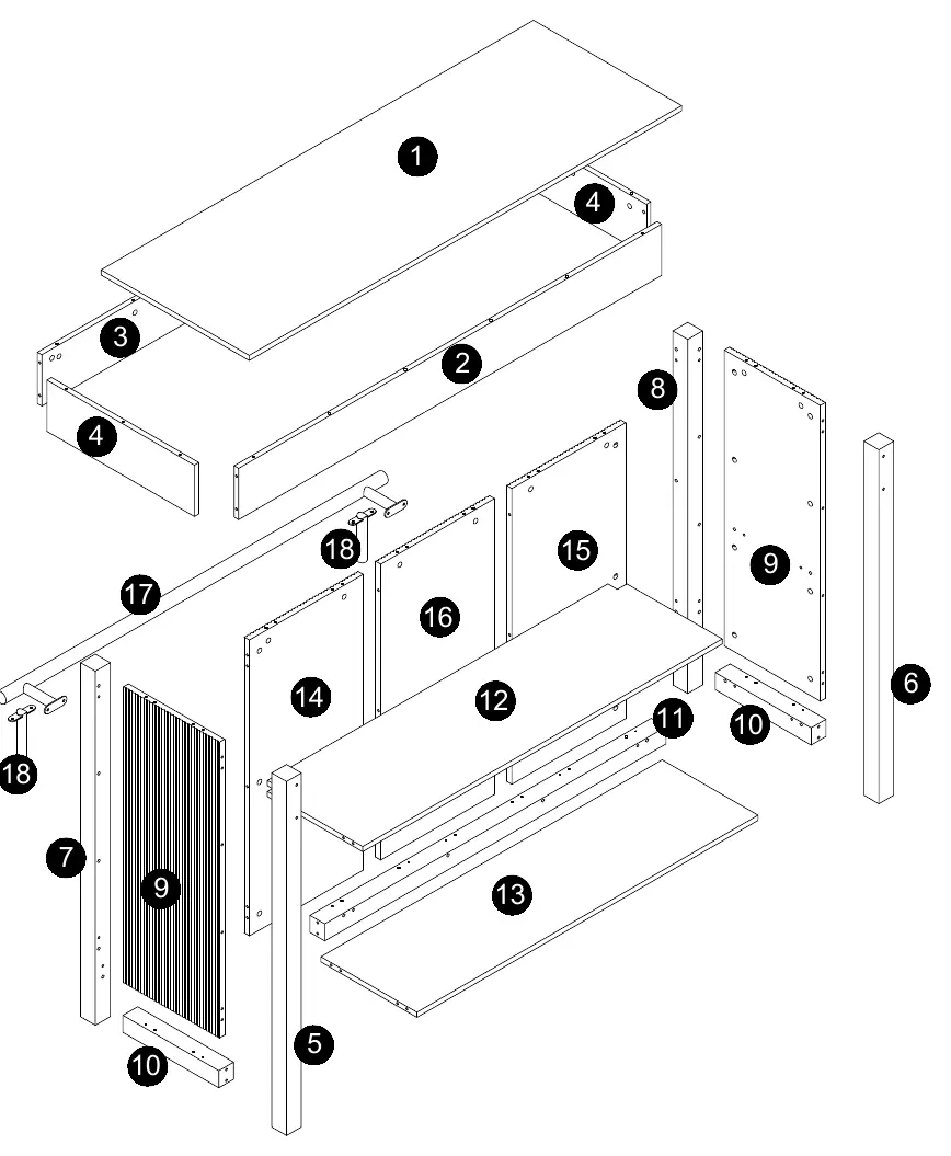
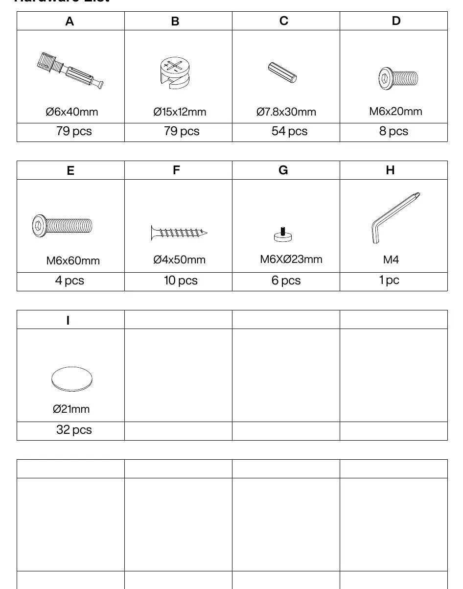
Parts and Hardware
The unit consists of various numbered board parts and labeled hardware (A-I). Ensure all items listed in the Parts List and Hardware List are present before assembly. Most board parts are labeled or stamped on the raw edge.
Assembly Preparation
The assembly relies heavily on a cam lock and pin system. Proper installation is critical:
- Cams and Pins: Screw the pin into the hole. Align the head of the cam with the lock pin. Turn the cam head with a screwdriver until tightened.
- Plastic Inserts: If a plastic part does not press into the mounting hole, loosen the screw counter-clockwise or remove it, then try again. Once in place, tighten the screw clockwise.
Step-by-Step Assembly
The assembly process is divided into 20 steps:
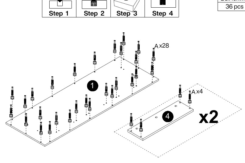
- Preparation: Install pins (A) into the main panels.
- Frame Assembly: Connect the side panels and shelves using the cam lock system (B) and wooden dowels (C).
- Structure: Assemble the main body, ensuring all cam locks are tightened correctly.
- Final Touches: Attach the footrest (17) and support legs (18) using the provided screws (D).
- Finishing: Apply protective covers (I) to exposed hardware where applicable.
Practical help
Common problems
Parts do not fit or are misaligned
Do not fully tighten screws until all parts are in place. Ensure cam locks are properly aligned with the pins.
Plastic part for cam/pin won't press in
Loosen the screw counter-clockwise or remove it from the plastic part, press the plastic part into the hole, then tighten the screw clockwise.
Surface scratches during assembly
Assemble the furniture on a soft, smooth surface, such as a rug or carpet.
Before use
- Verify all parts are present using the Parts List.
- Verify all hardware (A-I) is present using the Hardware List.
- Prepare a soft, smooth assembly surface.
- Use hand tools for assembly.
- If using an electric screwdriver, set to low power/torque.
Images and diagrams
- The manual uses an exploded view diagram on page 4 to identify all numbered parts.
- Step-by-step diagrams show the exact orientation of panels and hardware placement.

Manual page author
David Miller
Documentation analyst
Organizes user manual content into clear summaries, with attention to model details, product context, and everyday usability.