Power / Uninterruptible Power Supplies
User Manual for Avocent DSR1024 KVM Switch
Quick guide for the Avocent DSR1024 KVM Switch. Learn how to install, connect hardware, configure network settings, and adjust mouse settings for remote access.
Table of contents
Manual images
Click an image to enlargeQuick guide from the manual
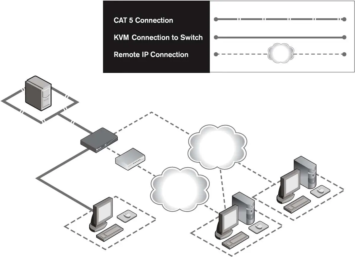
The Avocent DSR1024 is a KVM (Keyboard, Video, Mouse) switch designed for centralized control of data center servers. It supports both analog (local) and digital (remote) connectivity. This guide provides essential steps for hardware installation, network configuration, and mouse optimization for remote sessions.
Product Overview
The DSR1024 switch allows users to access target devices via a 100BaseT Ethernet connection or a modem. It utilizes DSRIQ modules to reduce cable bulk, connecting to target servers via standard CAT 5 UTP cabling. The switch supports video resolutions up to 1280 x 1024 for remote users and 1600 x 1200 for local users.
Installation
Follow these steps to set up your DSR1024 switch:

- Power Down: Ensure all target devices are powered off before making connections.
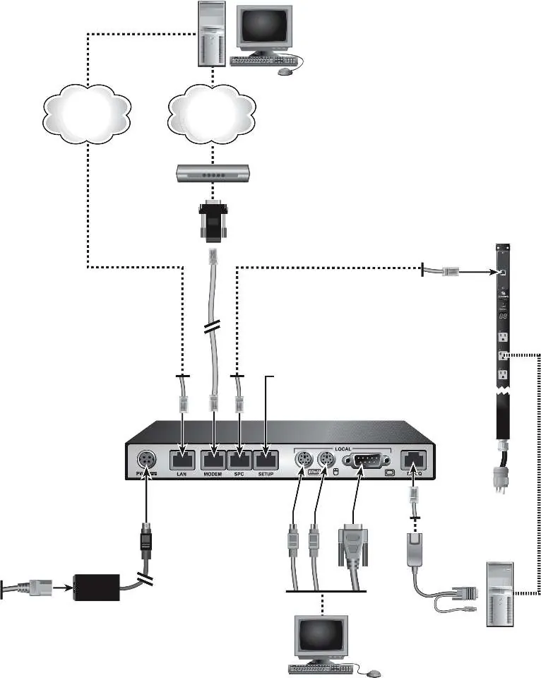
- Local Connections: Connect your VGA monitor, PS/2 keyboard, and mouse to the local ports on the switch. Both keyboard and mouse must be installed for proper initialization.
- Target Connections: Connect one end of a CAT 5 patch cable to the DSRIQ port on the switch and the other to a DSRIQ module. Attach the DSRIQ module to the target server.
- Network: Connect an Ethernet cable to the LAN port for network access.
- Optional Modem: If using a modem, connect it to the MODEM port using the provided ribbon cable and RJ-45 to DB-9 adaptor.
- Power Up: Power on the target device first, then the DSR1024 switch. Wait approximately one minute for initialization.
Network Configuration
While DSView software is the preferred method for configuration, you can use the Console menu via the SETUP port:
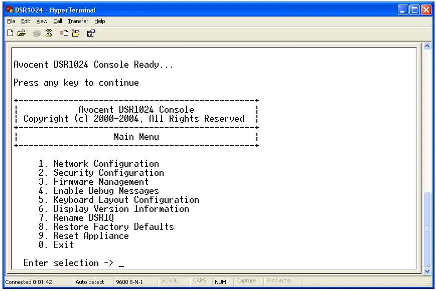
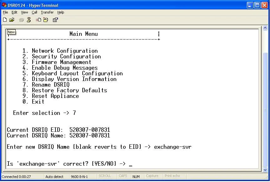
- Connect a terminal or PC running terminal emulation software (e.g., HyperTerminal) to the SETUP port.
- Configure the terminal settings to 9600 bps, 8 bits, 1 stop bit, no parity, and no flow control.
- Power on the switch and press any key after initialization to access the Console Main Menu.
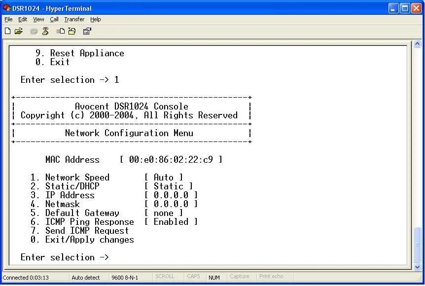
- Select 1. Network Configuration to set the network speed, IP address, netmask, and default gateway.
Adjusting Mouse Settings
For remote control to function correctly, you must adjust mouse settings on the target computer:
- Windows NT: Set Pointer speed to Slow and Acceleration to None.
- Windows 2000/XP/Server 2003: Set speed to 50% and disable 'Enhance pointer precision'.
- Linux/Solaris: Follow specific driver settings provided in the manual to ensure proper mouse sync.
- Alignment: Always click Mouse Align in the DSView remote session window after making adjustments.
Firmware and Maintenance
Firmware can be updated via the DSView software or the Console menu using a TFTP server. Caution: Do not disconnect DSRIQ modules or cycle power during a firmware update, as this may render the module inoperable.
Technical Specifications
- Video Resolution: Up to 1280 x 1024 @ 75 Hz (Remote).
- Cabling: 4-pair UTP CAT 5 or CAT 6 (max 10 meters).
- Operating Temperature: 0 to 40°C (32 to 104°F).
- Power: 100-240 VAC, 50-60 Hz.
Practical help
Common problems
Keyboard not initializing
Ensure both a keyboard and mouse are connected to the local port.
Mouse sync issues in remote session
Adjust mouse speed and acceleration settings in the OS (e.g., set to Slow/None for Windows NT) and click 'Mouse Align' in the DSView window.
Network connection failure
Verify IP address, netmask, and gateway settings via the Console menu; ensure the Ethernet cable is securely connected.
Before use
- Power down all target devices.
- Verify you have a CAT 5 patch cable (up to 10m).
- Ensure you have the correct DSRIQ module (PS/2, USB, or Serial).
- Connect VGA monitor and PS/2 keyboard/mouse to local ports.
- Connect Ethernet cable to LAN port.
Specs in practice
- Video Resolution
- Supports up to 1280 x 1024 for remote users and 1600 x 1200 for local users.
- Console Port
- Serial RS-232 port used for initial configuration (9600 bps, 8-N-1).
- Operating Temperature
- 0 to 40°C (32 to 104°F) for safe operation.
Images and diagrams
- Figure 1.1: Overview of the DSR1024 switch configuration including analog and digital user access.
- Figure 2.1: Detailed wiring diagram showing connections between the switch, target server, and SPC power control device.
Model compatibility
- Supports DSRIQ-PS/2, DSRIQ-USB, DSRIQ-VSN (Sun VGA), DSRIQ-WSN (Sun 13W3), and DSRIQ-SRL modules.
- Requires DSView Server software for full management.

Manual page author
David Miller
Documentation analyst
Organizes user manual content into clear summaries, with attention to model details, product context, and everyday usability.